|
A standard, 40-wire IDE/ATA cable. Note the presence of
three black |
Standard (40-Conductor) IDE/ATA Cables
Each IDE/ATA channel uses one IDE/ATA cable. The cable that has been used for over a decade on this interface was once just called "an IDE cable", since there was only one kind (with the exception of special cable select cables.) Today, however, there is also the new 80-conductor Ultra DMA cable; to avoid confusion, I refer to the old cable as a standard 40-conductor cable.
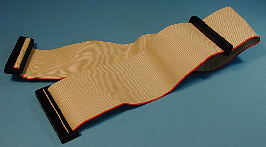
A standard IDE cable is a rather simple affair: a flat ribbon cable, normally gray in color, with a (usually red) stripe running down the edge. The cable has 40 wire connectors in it, and usually has three identical female connectors: one is intended for the IDE controller (or motherboard header for PCs with built in PCI ATA controllers) and the other two are for the master and slave devices on the interface. The stripe is used to line up pin 1 on the controller (or motherboard) with pin 1 on the devices being connected, since the techniques used for keying the cables are not standardized. For more information on IDE/ATA connectors and signals, see this page.
|
A standard, 40-wire IDE/ATA cable. Note the presence of
three black |
Some cheapskate PC makers that ship PCs with only one IDE device per channel save a few pennies by using an interface cable that has only two connectors. This means you can't use two IDE devices on a channel, unless you replace the cable with one that has three connectors. Fortunately this is easy to do, and the cables are cheap and readily available at most any store that sells computer supplies and parts (this is also a great component to buy cheap at a computer show). Even more fortunately, most companies don't do this any more.
In many ways, the cable is the weak link in the IDE/ATA interface. It was originally designed for very slow hard disks that transferred less than 5 MB/s, not the high-speed devices of today. Flat ribbon cables have no insulation or protection from electromagnetic interference. Of course, these are reasons why the 80-conductor cable was developed for Ultra DMA. However, even with slower transfer modes there are limitations on how the cable can be used.
The main issue is the length of the cable. The longer the cable, the more the chance of data corruption due to interference on the cable and uneven signal propagation, and therefore, it is often recommended that the cable be kept as short as possible. According to the ATA standards, the official maximum length is 18 inches, but if you suspect problems with your hard disk you may find that a shorter cable will eliminate them. Sometimes moving where the disks are physically installed in the system case will let you use a shorter cable.
![]() Warning: There are
companies that sell 24" and even 36" IDE cables. They are not recommended
because they can lead to data corruption and other problems. Many people use these with
success, but many people do a lot of things they shouldn't and get away with it.
:^)
Warning: There are
companies that sell 24" and even 36" IDE cables. They are not recommended
because they can lead to data corruption and other problems. Many people use these with
success, but many people do a lot of things they shouldn't and get away with it.
:^)
In terms of its mechanics, the IDE cable could certainly be much better designed as well. As described here, a keying mechanism exists to prevent incorrect cable insertion, but it's not universally implemented. This means there is the risk of inserting the cable backwards--the red stripe on the cable should be used to align pin 1 of the IDE/ATA device with pin 1 of the controller's connector port. Also, the cable has no latching mechanism, so it is not very securely attached to the hard disk or the motherboard. If you work inside the box and apply any pressure on the cable by accident, it can easily come loose (sometimes only partially) which will lead to device failure. Fortunately, neither backwards insertion or a partially loose cable usually cause any permanent damage--your hard disk just won't work.
Assuming cable select is not being used, any connector on a standard 40-conductor cable can go to any device, because all 40 wires are connected "straight through" to all three connectors. Since two of the connectors are closer to each other than the third, the distant connector is normally attached to the motherboard (or hard disk controller card). The other two devices can be used for either the master or the slave, and it doesn't matter which is which. If a single device is used, it should be attached to the connector at the end of the cable, and the connector in the middle of the cable left unattached. Using the middle connector and leaving the end connector unattached is technically allowed for regular PIO and DMA transfer modes, but leaves part of the cable "dangling". This is called a stub and creates much worse electrical characteristics on the cable, due to reflections from the unterminated ends of the cable wires. It is not recommended.
![]() Tip: The new 80-conductor
cable is compatible with regular 40-conductor cables (not cable select cables). If you are
having integrity problems with an older system using a 40-conductor cable, try replacing
it with one of the newer cables, which are superior electrically to the older design. Many
people now use the 80-conductor cables exclusively on all systems, even ones not using
Ultra DMA.
Tip: The new 80-conductor
cable is compatible with regular 40-conductor cables (not cable select cables). If you are
having integrity problems with an older system using a 40-conductor cable, try replacing
it with one of the newer cables, which are superior electrically to the older design. Many
people now use the 80-conductor cables exclusively on all systems, even ones not using
Ultra DMA.