SCART CONNECTOR PINOUT Table 1
Table 1 was the original and allows for composite video input/output, RGB inputs and stereo audio.
Table 2 was added to take S-video (S-VHS and Hi-8) inputs. This made pin 15 chrominance and pin 20 luminance.
Many TV sets have 2 SCART sockets. One is usually loke table 1 and the other like table 2, and pin 20 switchable from composite to S-Video luminance. The first can switch from a composite input to RGB input. The second can switch from a composite input to an S-Video input, pin 20 being either composite in or luminance in. Usually the second socket outputs a selectable composite signal on pin 19. |
 |
||
| Pin | Signal | Level | Impedance |
| 1 | Audio Out Right | 0.5 V rms | <1k ohm |
| 2 | Audio In Right | 0.5 V rms | >10k ohm |
| 3 | Audio Out Left + Mono | 0.5 V rms | <1k ohm |
| 4 | Ground Audio | ||
| 5 | RGB Ground Blue | ||
| 6 | Audio In Left + Mono | 0.5 V rms | >10k ohm |
| 7 | RGB Blue In | 0.7 V | 75 ohm |
| 8 | Audio/RGB switch / 16:9 | High (9.5-12V) AVmode Low (0-2V) TVmode |
>10kohm |
| 9 | RGB Ground Green | ||
| 10 | Comms Data 2 | ||
| 11 | RGB Green In | 0.7 V | 75 ohm |
| 12 | Comms Data 1 | ||
| 13 | RGB Ground Red | ||
| 14 | Ground Data | ||
| 15 | RGB Red In / Chrominance | 0.7 V (Chrom.: 0.3 V burst) | 75 ohm |
| 16 | Blanking Signal | High (1-3V) RGB Low (0-0.4V) Composite |
75 ohm |
| 17 | Ground Composite Video | ||
| 18 | Ground Blanking Signal | ||
| 19 | Composite Video Out | 1V including sync | 75 ohm |
| 20 | Composite Video In | 1V including sync | 75 ohm |
| 21 | Ground/Shield (Chassis) | ||
SCART CONNECTOR PINOUT Table 2
| Pin | Signal | Level | Impedance |
| 1 | Audio Out Right | 0.5 V rms | <1k ohm |
| 2 | Audio In Right | 0.5 V rms | >10k ohm |
| 3 | Audio Out Left + Mono | 0.5 V rms | <1k ohm |
| 4 | Ground Audio | ||
| 5 | RGB Ground Blue | ||
| 6 | Audio In Left + Mono | 0.5 V rms | >10k ohm |
| 7 | - | - | - |
| 8 | Fuction Select | High (9.5-12V) AVmode Low (0-2V) TVmode |
>10kohm |
| 9 | RGB Ground Green | ||
| 10 | Comms Data 2 | ||
| 11 | - | - | - |
| 12 | Comms Data 1 | ||
| 13 | Ground (chrominance) | ||
| 14 | Ground Data | ||
| 15 | Chrominance input | 0.3V | 75 ohm |
| 16 | - | - | - |
| 17 | Ground (luminance) | ||
| 18 | - | - | - |
| 19 | Video output (composite) | 1V including sync | 75 ohm |
| 20 | Luminance input | 1V including sync | 75 ohm |
| 21 | Ground/Shield (Chassis) |
| Cable between VCR and TV (Scart) | |||
| TV | VCR | ||
| Audio Right Out | 1 | 2 | Audio Right In |
| Audio Right In | 2 | 1 | Audio Right Out |
| Audio Left Out | 3 | 6 | Audio Left In |
| Audio Left In | 6 | 3 | Audio Left Out |
| Audio Ground | 4 | 4 | Audio Ground |
| Red | 15 | 15 | Red |
| Red Ground | 13 | 13 | Red Ground |
| Green | 11 | 11 | Green |
| Green Ground | 9 | 9 | Green Ground |
| Blue | 7 | 7 | Blue |
| Blue Ground | 5 | 5 | Blue Ground |
| Status / 16:9 | 8 | 8 | Status / 16:9 |
| Reserved | 10 | 10 | Reserved |
| Reserved | 12 | 12 | Reserved |
| Fast Blanking Ground | 14 | 14 | Fast Blanking Ground |
| Fast Blanking | 16 | 16 | Fast Blanking |
| Video Out Ground | 17 | 18 | Video In Ground |
| Video In Ground | 18 | 17 | Video Out Ground |
| Video Out | 19 | 20 | Video In |
| Video In | 20 | 19 | Video Out |
| Ground | 21 | 21 | Ground |
| S-Video Cable for Scart S-Video Input | ||
| S-Video Out | TV, Scart (Input) | |
| Luminance Out (Y) | 20 | Luminance In |
| Chrominance Out (C) | 15 | Chrominance In |
| GND | 4+17 | GND |
| Audio Out L | 2 | Audio In L |
| Audio Out R | 6 | Audio In R |
| S-Video Connection Pinout | ||||
| PIN | DESCRIPTION | Impedance | Level | |
| 1 | GND | Ground (Y) | ||
| 2 | GND | Ground (C) | ||
| 3 | Y | Intensity (Luminance) | 75 Ohms | 1V incl. Sync. |
| 4 | C | Color (Chrominance) | 75 Ohms | 0.3V Burst |
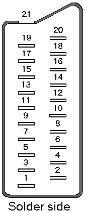
 View to the solder side View to the solder side of the male connector | ||||