UNIX Unleashed, System Administrator's Edition
- 20 -
Networking
by Salim Douba
Over the past few years, computer networks have become an increasingly integral part of most major production environments. Besides basic file and print services that users can transparently share, networks allowed them to use an ever-expanding suite of other productivity tools such as electronic mail, calendering, and imaging and voice/video conferencing applications. Another factor for the increased popularity of networks in production environments is the Internet. For many organizations, the Internet provided them with yet another business vehicle that they can use to promote their productivity and market reach--let alone the added capability of connecting remote branch offices to the headquarters via the Internet.
For the above reasons, implementing and maintaining networks that can meet the user demands on networked resources and productivity tools are becoming increasingly challenging tasks. UNIX networks are no less challenging than others. If anything, the task of installing and configuring UNIX networks is more complex than others. The complexity stems from the nature of protocols that underlie UNIX networks, namely the TCP/IP (Transmission Control Protocol/Internet Protocol) suit.
This chapter covers the necessary concepts and skills that the UNIX system administrator needs to possess in order to install, configure, and maintain UNIX connectivity. The first part is an overview of the basic concepts that govern TCP/IP communications, and second part provides a detailed treatment of the necessary UNIX tools and skill sets for achieving the objective of maintaining UNIX connectivity.
Basics of TCP/IP Communications
In 1969, the Defense Advanced Research Project Agency (DARPA) was given the mandate of looking at developing an experimental packet-switch network. The objective was to connect all government computing resources to a single global network without regard to the hardware or operating system platforms supporting these resources. Consequently, an experimental network, called ARPANET, was built for use in the development and testing of communications protocols that fulfill the assigned mandate. TCP/IP communication protocol suite is a direct product of this effort. Using TCP/IP, large networks connecting hybrid platforms (not just UNIX platforms) can be built. Anything from mainframes to desktop computers can be made to belong to, and communicate across, the same TCP/IP network--there is no better manifestation of this capability than the Internet itself which connects over 10 million computers from vendors the world over.
Request for Comments (RFCs)
Throughout the chapter, as well as some others in this book, references will be made to standard documents that contain the description and formal specification of the TCP/IP protocols being discussed in the form of RFC XXXX, where XXXX refers to the number of the document. For example, RFC 959 is the standards document specifying the File Transfer Protocol. Inquisitive readers might find reading some of the RFCs useful in order to better understand the issues at hand, or even sort problems encountered on their networks. Obtaining copies of the RFCs is a simple matter provided you have access to the Internet. One way of doing it is to send an e-mail to rfc-info@ISI.EDU, using the following format:To: rfc@ISI.EDU
Subject: getting rfcs
help: ways_to_get_rfcsIn response to this message, you get an e-mail detailing ways by which you can gain access to the RFCs. Methods include FTP, WWW sites, and e-mail.
TCP/IP Protocol Architecture
The TCP/IP communications suite was designed with modularity in mind. This means that instead of developing a solution which integrates all aspects of communications in one single piece of code, the designers wisely chose to break the puzzle into its constituent components and deal with them individually while recognizing the interdependence tying the pieces together. Thus, TCP/IP evolved into a suite of protocols specifying interdependent solutions to the different pieces of the communications puzzle. This approach to problem solving is normally referred to as the layering approach. Consequently, hereafter, reference will be made to the TCP/IP suite as a layered suite of communications.
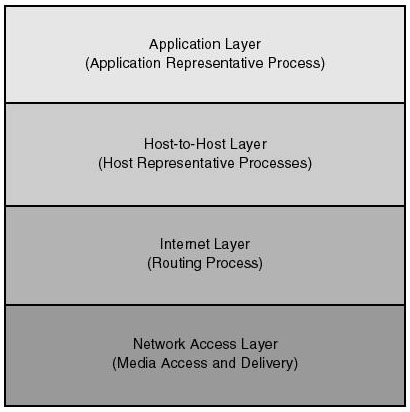
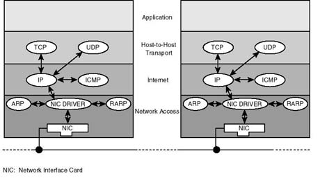
Figure 20.1 shows the four-layer model of the TCP/IP communications architecture. As shown in the diagram, the model is based on an understanding of data communications that involves four sets of interdependent processes: application representative processes, host representative processes, network representative processes, and media access and delivery representative process. Each set of processes takes care of the needs of entities it represents whenever an application engages in the exchange of data with its counterpart on the network. These process sets are grouped into the following four layers: application layer, host-to-host (also known as transport) layer, internet layer, and network access layer. Each of these layers may be implemented in separate, yet interdependent, pieces of software code.
Figure 20.1.
TCP/IP layered communications architecture.
Application Layer Application representative processes take care of reconciling differences in the data syntax between the platforms on which the communicating applications are running. Communicating with an IBM mainframe, for example, might involve character translation between the EBCDIC and ASCII character sets. While performing the translation task the application layer (for instance, application representative process) need not have (and shouldn't care to have) any understanding of how the underlying protocols (for instance, at the host-to-host layer) handles the transmission of translated characters between hosts. Examples of protocols supported at the application layer include FTP, TELNET, NFS, and DNS.
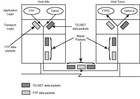
Host-to-Host Transport Layer Host representative processes (for example, the host-to-host, or transport, layer) take care of communicating data reliably between applications running on hosts across the network. It is the responsibility of the host representative process to guarantee the reliability and integrity of the data being exchanged, without confusing the identities of the communication applications. For this reason the host-to-host layer is provided with the mechanism necessary to allow it to make the distinction between the applications on whose behalf it is making data deliveries. In other words, assume that two hosts, tenor and alto, are connected to the same network, as shown in Figure 20.2. Furthermore, assume that a user on host alto is logged in to FTP on host tenor. Also, while using FTP to transfer files, the user is utilizing TELNET to login in to host tenor to edit a document.
In this scenario, data exchanged between both hosts could be due to TELNET, FTP, or both. It is the responsibility of the host-to-host layer, hereafter called the transport layer, to make sure that data is sent and delivered to its intended party. What originates from FTP at either end of the connection should be delivered to FTP at the other end. Likewise, TELNET-generated traffic should be delivered to TELNET at the other end, not to FTP. To achieve this, as will be discussed later, the transport layer at both ends of the connection must cooperate in clearly marking data packets so that the nature of the communicating applications is easily identifiable. Protocols operating at the transport layer include both UDP (User Datagram Protocol) and TCP (Transmission Control Protocol). Later sections will cover the characteristics of both protocols.
Figure 20.2.
Host-to-host (transport layer) is responsible for connecting applications and for
delivering data to its destined process.
Internet Layer The internet layer is responsible for determining the best route that data packets should follow to reach their destination. If the destination host is attached to the same network, data is delivered directly to that host by the network access layer; otherwise, if the host belongs to some other network, the internet layer employs a routing process for discovering the route to that host. Once the route is discovered, data is delivered through intermediate devices, called routers, to its destination. Routers are special devices with connections to two or more networks. Every router contains an implementation of TCP/IP up to and including the internet layer.
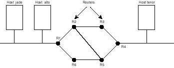
As shown in Figure 20.3, hosts alto and tenor belong to different networks. The intervening networks are connected via devices called routers. For host alto to deliver data to host tenor, it has to send its data to router R1 first. Router R1 delivers to R2 and so on until the data packet makes it to host tenor. The "passing-the-buck" process is known as routing and is responsible for delivering data to its ultimate destination. Each of the involved routers is responsible for assisting in the delivery process, including identifying the next router to deliver to in the direction of the desired destination. The protocols that operate at the internet layer include IP (Internet Protocol), and RIP (Route Information Protocol) among others.
Figure 20.3.
Routers cooperate in the delivery of data packets to their destinations.
Network Access Layer The network access layer is where media access and transmission mechanisms take place. At this layer, both the hardware and the software drivers are implemented. The protocols at this layer provide the means for the system to deliver data to other devices on a directly attached network. This is the only layer that is aware of the physical characteristics of the underlying network, including rules of access, data frame (name of a unit of data at this layer) structure, and addressing.
While the network access layer is equipped with the means for delivering data to devices on a directly attached network, it does so based on directions from IP at the internet layer. To understand the implications of this statement, look at the internetwork of Figure 20.3. Hosts jade and alto are said to belong to the same network since they are directly attached to the same physical wire. In contrast, host tenor belongs to a different network.
When a requirement arises to deliver data out of host alto, the internet layer (in particular the IP protocol) has to determine whether the destined host is directly attached to the same network. If so, IP passes the data packet to the network access layer and instructs it to deliver the data to the designated host. So, should, for example, the packet be destined to host jade, IP instructs the network access layer to take the necessary steps to deliver it to that host.
However, if IP on host alto is required to deliver the data packet to a host on a different network (for instance, host tenor), IP has to determine to which network the host belongs and how to get the packet there. As can be seen from the diagram, to deliver packets to host tenor, IP in host alto has to send the packet first to router R1, then R1 in turn has to forward it to R2 (or R3), and so on, as explained in the previous subsection. Consequently, IP passes the packet on to the network access layer and instructs it to deliver the packet to router R1. Notice how in both cases, the case of a host directly attached to same network (host jade) and the case of a host on different network (host tenor), the network access layer followed the addressing instructions imposed by IP at the internet layer. In other words, the network access layer relies on IP at the layer above it to know where to send the data.
TCP/IP Data Encapsulation
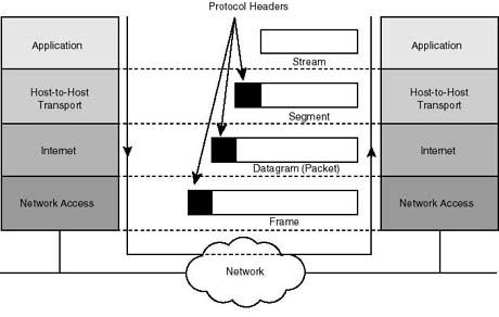
As data is passed down the layers, the protocol handling it at that layer adds its own control information before passing the data down to the layer below it. This control information is called the protocol header (simply because it's prepended to the data to be transmitted) and is meant to assist in the delivery of user data. Each layer is oblivious to the headers added to the user data by the layers above it. The process of adding headers to the user data is called data encapsulation.
Using headers, TCP/IP protocols engage in peer talk with their counterparts across the network. As shown in Figure 20.4, when data reaches its ultimate destination, each layer strips off its header information before passing the data on to the layer above. Subsequently, each header is interpreted and used in the handling of the user data.
Figure 20.4.
Data encapsulation under TCP/IP. All headers but the network access layer's remain
the same. The network access layer's header is a function of the underlying physical
network.
Following are examples of what each header can contain:
- At the transport layer, the header contents include destination and source port
numbers. These are treated as process identification numbers, which help in the exchange
of encapsulated data between designated processes, without confusing these processes
with others that might be running simultaneously on the same involved hosts. The
data and header at this layer form a data unit referred to as a data segment.
- At the internet layer, the header also contains the IP addresses identifying
the ultimate communicating end systems. The data and header information at this layer
are referred to as an IP datagram.
- At the network access layer, the header includes the media access control (MAC) addresses of source and destination devices on the same physical network. The data unit formed at this layer is referred to as data frame.
The Network Access Layer
The network access layer is responsible for the delivery of data to devices connected to the same physical network. It is the only layer that is aware of the details of the underlying network. In other words, the network access layer is aware of details such as the media type (unshielded twisted pair, fiber, coax, and so on), electronic encoding of data, and media access method. Given that TCP/IP formalizes the exchange of data across protocol boundaries in the same host, you can see how a new network access technology can be implemented without affecting the rest of the protocol hierarchy. Ethernet and Token-ring are examples of underlying technologies that the network access layer relies on to receive data from, or deliver data to, the network.
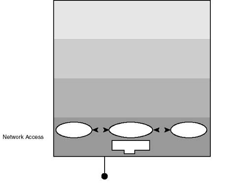
The network access layer implementation includes the network interface card (that is, the communications hardware) that complies with the communications media, and the protocols that handle all the action (see Figure 20.5). An example of protocols implemented at this level is the Address Resolution Protocol (ARP, discussed in the "Address Resolution Protocol" section), which takes care of mapping the IP symbolic address to the corresponding hardware (MAC) address. It is worth noting from the diagram, that not all data that the network interface card (NIC) receives from the network is passed up the layer hierarchy. Some data might have to be passed by the MAC driver to adjacent protocols coexisting with the driver at the network access layer (for example, Reverse Address Resolution Protocol, discussed later in the chapter). This feature is commonly known as data multiplexing.
Figure 20.5.
The network access layer is aware of the details of the underlying physical network.
It includes protocols implemented in software as well as the network interface card.
Among other functions, the network access layer encapsulates data that is passed to it by the internet layer into frames for subsequent delivery to the network. Keep in mind, however, that the frame format is a function of the media access technology in use, whereas the data format of upper layer protocols never changes.
The Internet Layer
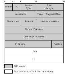
Two protocols are implemented at this level: the Internet Control Message Protocol (ICMP, RFC792), and the Internet Protocol (RFC791). The purpose of the Internet Protocol (IP) is to handle routing of data around the internetwork (commonly known as the internet), while that of ICMP is to handle routing error detection and recovery. IP is the cornerstone of the TCP/IP suite of protocols. All TCP/IP protocols communicate with their peers on the network by riding IP datagrams. Figure 20.6 shows the data structure of the IP datagram (including both the IP header and data passed on from the layer above). IP's header fields are presented in the following discussion of its functions. But first, take a look at its two main characteristics.
Figure 20.6.
IP datagram structure. The shaded part is IP's header. IP is oblivious to the
contents of the data field passed on by the protocol in the layer above.
Main Characteristics of IP IP is a connectionless protocol. This means that IP does not attempt to establish a connection with its peer prior to sending data to it. A connection oriented protocol undergoes a sort of handshake with its peer in the remote system; the purpose of the handshake is twofold: it verifies the readiness of the remote peer to receive data before it is sent; and during the handshake both ends of the connection try to reach a mutual agreement on some of the parameters that should govern the data exchange process. An example of a negotiated parameter is the maximum size of the data unit that can be exchanged during the connection.
In addition to being connectionless, IP delivers an unreliable service. The unreliability stems from the fact that IP does not provide error detection and recovery. All that IP cares about is the delivery of data to its designated destination. What happens to the datagram during shipment is a concern that is delegated, by design, to IP service users (higher layer protocols). This is very much similar to the postal service, which delivers mail on a best effort basis, while not caring about the quality of what is being shipped or received.
Functions of IP
IP functions include:
Data encapsulation and header formatting
Data routing across the internetwork
Passing data to other protocols
Fragmentation and reassembly
Data Encapsulation Data encapsulation involves accepting data from the transport layer, and adding to it IP's header control information. As shown in Figure 20.6, the IP header is five or six 32-bit words in length; this is because the sixth word is optional, justifying the IHL field (the Internet Header Length). The first field refers to the version of IP in use, with the current one being number 4. The third field is the type-of-service field (TOS). TOS can be set to specify a desired class of service, as requested by applications. Examples of class of service supported by IP are: minimum delay, which is requested by application protocols such as RLOGIN and TELNET, and maximum throughput, which is requested by applications such as FTP and SMTP.
The total length field minus the IHL field indicate to IP the length of the data field. Both the identification and fragmentation fields will be discussed under Fragmentation and Reassembly below. The time to live (TTL) field is initialized by IP to the upper limit on the number of routers that a datagram can cross before it ultimately reaches its destination. Assuming that TTL was set to 32, it is decremented by one by each router it crosses. As soon as TTL reaches zero, the datagram is removed by the next router to detect the anomaly. The underlying idea is that with TTL, a lost datagram can be stopped from endless looping around the network. The protocol number field will be discussed later in this section.
Although IP is an unreliable protocol, in the sense that it does not perform error detection and recovery, it still cares about the integrity of its own control information header. With the help of the header checksum, IP verifies the integrity of data in the header fields. If the integrity check fails, IP simply discards the datagram. IP does not communicate a notification of the failure, also called negative acknowledgment, to the sending host.
The source and destination addresses are 32 bits in length. IP address classes and structure will be dealt with in more detail in the next subsection, "Data Routing." Addresses included in the address fields describe the identities of the ultimate communicating hosts. For example, whenever host alto (in Figure 20.3) is sending data to host tenor, the source and destination address fields will contain the 32-bit IP addresses of these hosts, respectively.
Finally, the options field, which may include other control information, is populated on an as-needed-basis, rendering it variable in size. An example of optional information is the route record, which includes the address of every router the datagram traversed during its trip on the network.
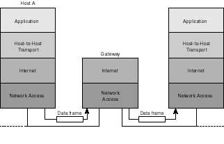
Data Routing Routing is perhaps the most important function that the internet layer performs. IP distinguishes between hosts and gateways. A gateway (see the following Note) in TCP/IP is actually a router that connects two or more networks for the purpose of providing forwarding services between them. Figure 20.7 shows a gateway forwarding a datagram between two networks.
A host is the end system where user applications run. By default, routing on hosts is limited to the delivery of the datagram directly to the remote system, if both hosts are attached to the same network. If not, IP delivers the datagram to a default gateway (i.e. router). The default gateway is defined on the host during TCP/IP configuration, and is a router attached to the same network, which the host should 'trust' for assistance in deliveries made to other hosts on remote networks.
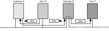
Figure 20.8 illustrates the concept of default routers. Host X in the diagram, is configured to gateway A as its default router. Accordingly, whenever X wants to send data to Y, it delivers the datagram to gateway A (its default router), not B. Upon examining the destination IP address, gateway A realizes that the address belongs to host Y, which is on a network to which gateway B is connected. Consequently, gateway A forwards the datagram to gateway B for the subsequent handling and delivery to host Y.
Routers and Gateways
Currently, the networking industry makes a distinction between a router and a gateway. Routers are said to provide routing services between networks supporting same network protocol stacks. Gateways, on the other hand, connect networks of dissimilar architectures (for example, TCP/IP and Novell's IPX/SPX). Historically, however, the TCP/IP community used the term gateway to refer to routing devices. Throughout this chapter, both terms are used interchangeably to refer to routing.
Figure 20.7.
A gateway providing routing services between two networks.
Figure 20.8.
A host on an IP network forwards all deliveries pertaining to remote networks to
its default router.
UNIX allows a host to attach to more than one network using multiple interface cards, each attaching to a different network. Such a host is commonly referred to as a multihomed host. Furthermore, a UNIX multihomed host can optionally be configured to route data between networks to which it is attached. In other words, it can be made to partly behave as a router. Otherwise, it behaves in exactly the same fashion as other hosts with a single interface card, the difference being that all hosts on networks to which it is attached can engage in the exchange of data with applications it supports.
Passing Data to Other Protocols It was mentioned earlier in the chapter that all TCP/IP protocols send their data in IP datagrams. Hence, to assist IP in submitting a datagram it receives from the wire to the intended protocol, a protocol field is included in IP's header. By TCP/IP standards, each protocol that uses IP routing services is assigned a protocol identification number. Setting the protocol field to 6, for example, designates the TCP protocol, whereas 1 designates the ICMP protocol. A protocol number of 0, however, designates the IP protocol, in which case encapsulated data is processed by IP itself. Figure 20.9 illustrates how the protocol field is used to sort datagrams for subsequent delivery to their destined protocols.
Figure 20.9.
When IP receives a datagram from the wire, it internally routes the datagram to one
of the shown protocols based on identification information contained in IP's header
protocol field.
Fragmentation and Reassembly As shown in Figure 20.6, the total length field in the IP header is 16 bits wide, which means that the largest datagram IP is allowed to handle is 64 Kilobytes (65535 bytes) in size. However, some underlying networks (media access technologies) do not tolerate as much data in a single frame. An Ethernet frame, for example, cannot exceed 1514 bytes. In cases like these, IP resorts to what is known as data fragmentation. Fragmentation takes place whenever data in sizes exceeding the frame capacity is passed to IP by another protocol, for subsequent handling on the network.
Although all data fragments are normally delivered using the same route, there is always a possibility that a few of them traverse alternate routes. This may happen due to rising congestion on paths followed by earlier fragments, or to link failure. Whatever the case may be, fragments following different routes stand the chance of reaching their destination out of the order in which they were sent. To allow for the recovery from such an eventuality, IP makes use of the fragmentation offset field in its header. The fragmentation offset field includes sequencing information, which the remote IP peer uses to reorder data fragments it receives from the network, and to detect missing packets. Data is not passed to the protocol described in the protocol field unless all related fragments are duly received and reordered. This process of fragment recovery and resequencing is known as data reassembly.
How does IP deal with situations where it is required to fragment two or more large datagrams at the same time? What if all data is being sent to the same remote host? How can the receiving host distinguish between fragments belonging to different datagrams? Well, the answer to these questions lies in the identification field. Fragments belonging to the same datagram are uniquely associated by including the same value in the identification field. The receiving end makes use of this value in order to recover the IP fragments to their respective datagrams.
Finally, you may be asking yourself these questions: How can a receiving IP tell whether data is fragmented? How does it know when all fragments are being sent? Answers to both questions lie in the header flags field. Among other bits, the flags field includes a more fragments bit, which is set "on" in all fragments belonging to a datagram, except for the final fragment.
The Internet Control Message Protocol The Internet Control Message Protocol (ICMP) forms an integral part of the IP protocol. It is the "messenger" that couriers messages between hosts. ICMP messages carry control, informational, and error recovery data. Below is a description of some of those messages:
- Source quench: This is a flow control message, which a receiving host
sends to the source, requesting that it stop sending data. This normally happens
as the receiving host's communications buffers are close to full.
- Route redirect: This is an informational message that a gateway sends
to the host seeking its routing services. A gateway sends this message to inform
the sending host about another gateway on the network, which it trusts to be closer
to the destination.
- Host unreachable: A gateway, or a system encountering a problem in the
delivery of a datagram (such as link failure, link congestion, or failing host),
sends a host unreachable error message. Normally, the ICMP packet includes
information describing the reason for unreachability.
- Echo request/echo reply: UNIX users commonly use the ping command (more on this later) to test for host reachability. When entered, ping invokes both ICMP messages: echo request, and echo reply. Echo request is sent from the host on which ping (covered in the "ping: Test for Reachability" section and throughout the chapter)was invoked to the remote system described on the command line. If the remote system is up and operational, it responds with an echo reply, which should be interpreted as proof of reachability.
You can invoke ICMP by using the UNIX ping command to check on the reachability of a remote host as shown here:
# ping 123.5.9.16
123.5.9.16 is alive
ping invokes an ICMP echo request message that is sent to the designated host. If, upon receiving the echo request, the host responds with an ICMP echo response message, it is reported as being alive (as shown in the example), and hence, reachable. Otherwise, the host is deemed not reachable.
IP Address Structure In TCP/IP, every device on the network derives its unique complete network address by virtue of an address assignment to which the device is configured (more on configuration later in the chapter). The reason the address is termed complete is because it is pretty much all that is needed to locate it on the network regardless of its size (similar to the postal address, which completely describes your home address--thus helping others to unambiguously locate you).
The assigned address is known as a symbolic IP address, and is made up of two parts: 1) the network address, which is common to all hosts and devices on the same physical network, and 2) the node address, which is unique to the host on that network. As you will see, neither part has anything to do with the actual hardwired MAC address on the network address card. As a matter of fact, a network administrator has the freedom to change the node part of the address (with some restrictions), and to a lesser degree the network address, irrespective of the MAC address. For this reason, the address is described as symbolic.
Confusing as it may initially sound, the IP protocol uses these symbolic addresses to route data on the network. In other words, when a user requests that a telnet session be established with another host, TCP/IP uses the administrator assigned 32-bit IP addresses in order to connect and establish the telnet session between both the requesting and the target hosts. The details of this are going to be tackled later in the chapter (refer to the "Address Resolution Protocol" section. First, have a look at how IP addresses are made, and the classes to which they belong.
The IP address is 32 bits (or four bytes) long, including both the network and the node addresses, and it occupies the IP source and destination address fields of the IP header. How many bits of the address belong to the network part, versus the number of bits that belong to the node part is dependent on the IP address class into which the address falls. IP defines three main classes: A, B, and C. There is a class D, which is lesser in significance than the other ones and will be touched on very briefly.
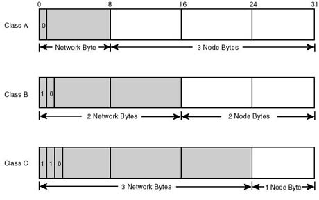
Figure 20.10 shows the different address formats corresponding to each of the three main classes that IP supports. Each IP address class is distinguishable by the very first few bits of the network portion. The following is a listing of the different IP classes and the rules by which they are governed:
Figure 20.10.
IP Address classes, and their corresponding structures.
Class A address: The first bit is fixed to 0, and the first byte is called the network id and identifies the network. The remaining three bytes are used to identify the host on the network, and comprise the host id. It can be calculated that there is a maximum of 127 class A networks, with each capable of accommodating millions of hosts.
Class B address: The first two bits are fixed to 10, the first and second byte are used to identify the network, and the last two bytes are used to identify the host. There can be 65,535 hosts on class B networks, capable of accommodating thousands of hosts.
Class C address: The first three bits are fixed to 110, the first, second, and third bytes are used to identify the network, and the last byte is used to identify the host. Class C networks are the smallest of all classes, as each can accommodate a maximum of 254 hosts (not 256, because 0x0 and 0xFF are reserved for other purposes). With three bytes reserved to identify the network, millions of class C networks can be defined.
Class D address: The first four bits are fixed to 1110. A class D address is a multicast address, identifying a group of computers that may be running a distributed application on the network. As such, class D does not describe a network of hosts on the wire.
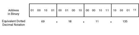
To make address administration a relatively easy task, TCP/IP network administrators can configure hosts, and routers, with addresses by using what is commonly known as dotted decimal notation. Dotted decimal notation treats the 32-bit address as four separate, yet contiguous, bytes. Each byte is represented by its decimal equivalent, which lies between 0 and 255 (the decimal range equivalent to an 8-bit binary pattern). Figure 20.11 shows an example of a class A address in both binary and dotted decimal (69.18.11.135) notation.
Figure 20.11.
IP address in binary and the equivalent dotted decimal notation.
Given that an 8-bit binary pattern can assume any decimal equivalent in the range of 0 to 255 and given the initial bits of a certain class, you should be able to tell from the first byte the class of the network. Table 20.1 below depicts the range of values for the first byte of each of the IP address that classes can assume.
Table 20.1. IP address classes and the range of values their respective first byte can assume.
| Address Class | Decimal Range |
| A | 0--127 |
| B | 128--191 |
| C | 192--223 |
Consider the address 148.29.4.121. By applying the rules learned above, it can be determined that this is a class B address, since the first byte lies in the 128 to 191 range of values. And since a class B address has the first two bytes for a network address, it can be derived that the network address is 148.29 while the host address is 4.121 on that network. To generalize, given an IP address, its class can be recognized by interpreting the first byte. Consequently, the network portion of the address can be derived from the remaining bytes.
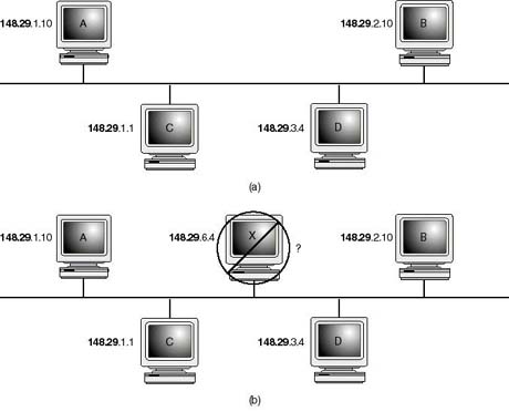
Figure 20.12 shows an example of a class B network. Notice how all the hosts have the 148.29 network address in common. A host misconfigured (for example, host X in Figure 4.4b) to any other network address will not be able to talk to other hosts on the network, be it on same physical network or other router connected networks. When a host or any other network device is assigned an IP address, IP derives its network class and network address from that assignment (148.29). Later, when it is required to deliver a datagram to a host, it compares the network address of the destination address submitted by the transport protocol (TCP or UDP) to that of its own. If the addresses match, IP refrains from routing the datagram (as explained earlier, the datagram won't be sent to a router for assistance in delivery). Instead, IP assumes that the host is on the same network and, therefore, attempts a direct delivery to the designated node address.
Figure 20.12.
(a) A properly configured network has all of the hosts belonging to it assigned the
same network address Host X is configured to a network address that is inconsistent
with the other hosts, resulting in routing conflicts.
Assuming that you are on host X and want to establish a file transfer session with host A on the network, you can enter the command:
ftp 148.29.1.10
Refer to the "Domain Name System" section later in this chapter to learn how to specify a host using a name instead of the IP address.
TCP picks up the address and passes it to IP, at the Internet layer, along with a TCP segment (which in turn contains the user request for FTP connection) that it wants delivered to host A. IP, on host X, compares its own network address (147.29) with that of host A (148.29). Since they are not the same, IP concludes that host A must belong to a remote network, and therefore direct delivery is not possible. For simplicity, assume that the network in Figure 20.4b is the only one in its environment, in which case there can be no routers on the wire. IP won't be able to forward the packet any further and will report a failure to deliver to the upper layer or application.
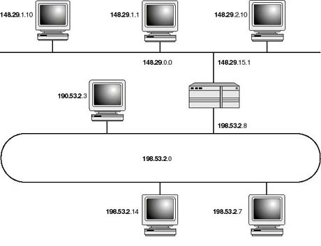
In Figure 20.13 you are shown two networks, a class B Ethernet network and a Token-ring class A network. A router is also shown connecting the two networks. An important observation to make is that the router is configured to two addresses, 148.29.15.1 and 198.53.2.8. The question that normally arises is, which of the two is the address? Well, as a matter of fact an address which you assign to the host is assigned to, or associated with, the network interface card that attaches the host to the network. Hence, in the case of a router and multihomed host, an address is required for every NIC card supported. Depending on which network the NIC attaches the host to, it must be assigned an IP address with a network part consistent with the network address assigned to the rest of the hosts community. Hosts on the Token-ring network use 198.53.2.8 to address the router, whereas those on Ethernet use 148.29.15.1.
Figure 20.13.
Routers are assigned as many addresses as network interface cards support.
You saw earlier that all 0s and all 1s (0x0 and 0xff, respectively) are reserved for special purposes, and therefore cannot be used to designate a node on the network. This is because an all 0s node address refers to all nodes on the network. For example, in the routing table of the router in Figure 20.13, a destination address of 198.53.2.0 refers to all hosts on the Token-ring network . While an all 1s node address is normally used to broadcast a message to all hosts on that network. Therefore, a host transmitting a broadcast message to 198.53.2.255 will have the message picked up by all active hosts on the Token-ring network only. Similarly, a broadcast to 148.29.255.255 will be picked up by all hosts on the Ethernet.
In addition to the reservations made on the node addresses described above, there are two class A network addresses that bear a special significance and cannot be used to designate a network. They are network addresses 0 and 127. Network 0 is used to designate the default route, whereas 127 is used to designate this host or the loopback address. As explained previously (refer to the "Data Routing" section) in this chapter, the default route refers to a router configuration that makes the routing of packets to destinations that are unknown to the router possible. The loopback address is used to designate the localhost and is used to send to the interface an IP datagram in exactly the same way other interfaces on the network are addressed. Conventionally, 127.0.0.1 is the address which is used to designate the local host. You can, however, use any other class A 127 address for the same purpose. For example 127.45.20.89 is valid for designating the local host as is the 127.0.0.1. This is because a datagram sent to the loopback interface must not, in any case, be transmitted on the wire.
Subnet Mask Class B networks accommodate approximately 65,000 hosts each, whereas Class A networks accommodate thousands of nodes. In practice, however, it is not feasible to put all on the same network. Here are two considerations:
- Limitations imposed by the underlying physical network: Depending on the
type of physical network, there is an upper limit on the number of hosts that can
be connected to the same network. Ethernet 10BASE-T, for example, imposes a limit
of 1,024 nodes per physical network.
- Network Traffic: Sometimes it might not be feasible even to reach the
maximum allowable limit of nodes on the underlying physical network. Depending on
the amount of traffic applications generate on the network you might have to resort
to breaking the network into smaller subnetworks to alleviate prevailing network
congestion conditions.
- Geographic Proximity: Organizations with branch offices across the nation or around the globe connect their computing resources over wide area network (WAN) links. This requires treating the branch office local area networks (LANs) as a network of interconnected networks--commonly referred to as internetwork (also as intranetwork).
In recognition of the eventual requirement that organizations might need to break their networks into smaller subnetworks, the TCP/IP protocol stack supports the use of same network address to achieve this objective. The use of same network address to implement a router-connected subnetworks is achieved by modifying the IP address structure, to extend the network ID portion beyond its default boundary. The mechanism for doing so is called subnet masking.
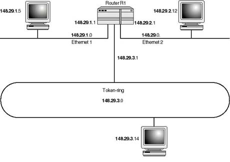
Because 148.29.0.0 is a Class B address, its default network ID consists of the two leftmost bytes (148.29), and the two lowest bytes are the node address (0.0). A network designer may choose to extend the network ID to include all of the second significant byte in order to break the network into smaller ones. Thus the only byte left for the node ID becomes the rightmost byte. Figure 20.14 illustrates the situation. As shown, each of the networks is now identified using the three left-most bytes (as though dealing with Class C networks). In other words, all hosts on the Token-ring network must have the 148.29.3 portion common to their addresses. Similarly, on the Ethernet networks, the 148.29.1 must be common to all addresses of hosts on the segment Ethernet 1, and 148.29.3 in common for all hosts on segment Ethernet 2.
Figure 20.14
A Class B address (148.29.0.0) being used on a subnetted network.
How does TCP/IP on a host or router know how to split the network address between the network ID and the host ID? Unless specified, TCP/IP assumes the default (16 bits for the network ID and 16 bits for the host ID for Class B addresses). To specify a different split, TCP/IP software supports a configuration parameter that is referred to as a subnet mask. Using a subnet mask, you can tell TCP/IP (in particular, IP protocol) which bytes constitute the network ID as opposed to the node ID.
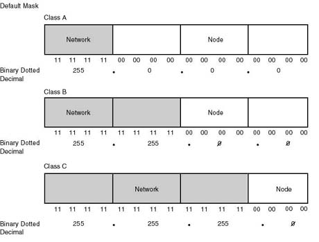
A subnet mask is a 32-bit number that is applied to an IP address to identify the network and node address of a host or router interface. As a rule, you are required to assign a binary 1 to those bits in the mask that correspond in position to the bits that you want IP to treat as part of the network ID. Similar to the IP address when specified, the subnet mask is normally using the dotted decimal notation. As such, the default subnet masks corresponding to Classes A, B, and C networks are 255.0.0.0, 255.255.0.0 and 255.255.255.0, respectively (see Figure 20.15). In order to extend the network ID to include the third byte in a Class B address, its subnet mask then becomes 255.255.255.0 (same as Class C's).
Figure 20.15.
Default subnet masks. Bits set to 1 in the mask correspond to the bits in the IP
address that should be treated as part of the network ID.
IP Routing Dynamics Now that we have enough of the needed background information, let's proceed to detailing the dynamics that govern the routing of data around the network. The depiction includes illustrations about some of the commonly useful and related UNIX commands.
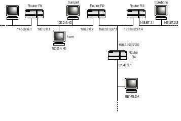
As explained earlier, routers take part in the delivery of data only if the data is being exchanged between hosts that are connected to two different networks. Data being exchanged between hosts on the same network is never routed. For example, should host trumpet need to send data to host horn, it sends it directly to host horn without asking for the intervention of any of the routers (R1 and R2). Consequently, the data packets being exchanged between both hosts never shows on other networks--they rather it remains local to the network that both hosts belong to.
The IP protocol decides whether the destined host belongs to the same network by comparing the network ID portion of that host with its host's. Whenever the network IDs of both the originating and destination hosts mismatch, the IP protocol tries to seek the help of a router on the same network. As a network may have more than one router connecting it to other networks, IP chooses the router it trusts to be closer to the designated destination. If one is found, the data packet is forwarded to that router. As will be explained in the next subsection, IP knows which of the routers to forward the data to by looking up a routing database called route information table (RIT).
Figure 20.16.
IP data routing.
In Figure 20.16, whenever host trumpet wants to deliver to host trombone, the following happens:
- 1. Host trumpet compares its network ID of 100 with that of host
trombone's of 148.67 (being Class B). Since they are different, the next
step is to seek a router's help.
2. IP in host trumpet searches its RIT for a router it trusts that is closer to the destination network (148.67). If the routing table is properly maintained, host trumpet identifies router R3 as being the desired router. Consequently, the data packet is forwarded to that router.
3. Router R3 receives the data packet and compares the destination address encapsulated in the Destination Address field of the IP packet to the ID of the networks to which it is connected. The outcome of the comparison allows router R3 to decide whether the designated host belongs to any of these networks. If so, the packet is sent directly to the host. Otherwise, router R3 goes through step 2 above. In our case, since host trombone belongs to network 148.67.0.0 (to which router R3 is directly attached), the comparison is favorable to sending the packet directly to that host.
Route Information Table (RIT) As mentioned in the previous section, IP protocol performs its routing function by consulting a database that contains information about routes (networks) that it recognizes. This database is called the route information table, and it is built and maintained by yet another protocol called the Route Information Protocol (RIP). RIP handles route discovery--that is, it is a process whose main purpose is to identify all the networks on the internetwork and the routers that are closest to each network. RIP is a protocol that runs on all hosts on routers. Hence, every RIP constructs and maintains the database (road map) from the perspective of the workstation or router in which it is running. The RIP includes the following information on each destination it recognizes on the internetwork:
- Distance: Serves as an indication of how far the destination is from the host
or router. Normally, it is equal to the number of intervening routers the datagram
has to go through to reach its destination. Distance is also referred to as the metric,
or number of hops.
- Next Router: Includes the IP address of the router that is trusted to be closer
to the destination, and therefore the datagram should be forwarded to in the delivery.
- Output Port: Specifies which of the network interfaces in the host (if multihomed) or router is attached to the same network as the next router.
For example, host trumpet's routing table (see Figure 20.16) would include an entry saying that it is 2 hops (the distance or metric) or routers away from network 148.67.0.0, and that the next router to deliver to is at address 100.0.0.2. Router R2's routing table entry would say that it is one router away from the same destination network (148.67.0.0), and that the next router to send the data to is R3.
The UNIX command to display the contents of the routing information table is netstat -rn as shown here:
# netstat -rn
Routing tables
Destination     Gateway            Flags    Refs     Use  Interface
127.0.0.1       127.0.0.1           UH      1        0      lo0
87.45.3.4       198.53.237.20       UGH     0        0      e3B0
100             100.0.0.2           U       4        51     wdn0
221.78.39       198.53.237.20       UG      0        0      e3B0
default         198.53.237.5        UG      0        0      e3B0
198.53.237      198.53.237.1        U       3        624    e3B0
Here is how to interpret each of the preceding columns:
- The Destination column includes to the address of the network or host.
When a host IP address is specified (as in the first and second entries), the destination
is referred to as specific route.
- The Gateway column refers to the next router.
- The Flags column provides status information about that route. Each of the characters in the Flags column describes a specific state. The interpretation of flag characters is
U: The route is up. This implies that the destination is reachable.
H: The route is specific, or leads, to a certain host (as shown in the first and second entries in the above example.
G: The route is indirectly accessible via other routers. If the G flag is not set it means that the router (or host) is directly connected to that route.
D: The route is created by the ICMP protocol's route redirect message.
- M: The route is modified by the ICMP protocol's route redirect message.
- The Refs column shows the number of active connections over that route. Active
connections can be due to ongoing FTP or TELNET sessions among others. Any service
or application that utilizes TCP as the underlying transport protocol increments
this column by one upon invocation.
- The Use column keeps track of the number of packets that traversed this route
since TCP/IP was started.
- The Interface column includes the name of the local interface from which the datagram should be forwarded to the next router. Upon configuring a network interface card, UNIX assigns it a label. For example, under SCO UNIX, e3B0 is the label assigned to the first 3c503 card in the host, whereas wdn0 refers to WD8003E interface card.
Route Table Maintenance TCP/IP supports both static and dynamic means of maintaining the routing table. Static means of maintaining the routing table mainly involve the use of the two UNIX commands: ifconfig and route add. Using ifconfig, a network interface card can be configured to an IP address and the applicable subnet mask as shown in the following example:
# ifconfig e3B0 100.0.0.2 255.0.0.0
Aside from configuring the interface (e3B0) to the specified address and subnet mask, the ifconfig command has the effect of updating the route information table with a static route information pertaining to the directly attached network (i.e. 100.0.0.0) as shown in the previous listing of the output of netstat -rn command.
Using the route add command a static route can be entered to the routing table of a UNIX host. The syntax of the route command is:
route add destination_address next_router metric
in which destination_address is the route you want to add to the routing table.
next_router is the address of the next router to forward the datagrams to.
metric is a measure of distance to the destination, normally expressed in number of intervening routers.
The following example shows how route add can be used to add a new destination to the routing table:
# route add 87.45.3.4 198.53.237.20 1
The following example shows how to use route add to configure a host for the default route entry:
# route add 0.0.0.0 198.53.237.5 1
By virtue of the preceding entry, the host in question is being configured to recognize the router at address 198.53.237.5 as being its default gateway.
Dynamic route maintenance involves the automatic addition of new discovered routes to the route table. It also involves deletions of routes that are no longer valid by virtue of network reconfiguration or due to failures. There are several protocols that might be employed for the task of dynamic route maintenance. Among the currently common ones are Route Information Protocol (RIP), Open Shortest Path First (OSPF), and Internet Control Messaging Protocol (ICMP). Of the three only ICMP was briefly discussed earlier in the chapter. For detailed treatment of all routing information protocols the reader is referred to the section "Networking".
Address Resolution Protocol (ARP) Every network interface card is guaranteed to have a unique 48-bit address hardwired to the card itself. This address is commonly referred to as Medium Access Layer (MAC) address. The IP address you assign to a host is independent of the MAC address which is hardwired on the network interface card in that host. As such, every host ends up maintaining two addresses, the IP address which is significant to TCP/IP protocols only, and the MAC address which is significant to the network access layer only. Data frames exchanged on the wire however, rely on the latter address, which indicates that there must be some sort of binding relation between these two forms of addresses. This section unravels this relationship. In particular, you will be shown how, given the IP address of a target host, the network access layer finds the corresponding MAC address, used later by the MAC protocol (e.g. Ethernet) to communicate data frames.
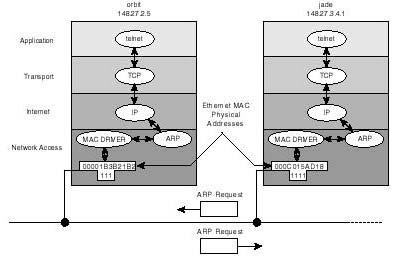
Figure 20.17 includes a depiction of the events which take place between two hosts when they try to talk to each other. In the diagram, both the IP address and the MAC layer addresses are shown for both hosts. It is assumed that a user on host jade wanted to establish a TELNET session with host orbit. The following is what happens:
Figure 20.17.
IP address to physical MAC address resolution using ARP protocol.
- 1. As a result of the user entering the command telnet jade,
the application (telnet, in this case) resolves the name jade to its corresponding
IP address. See the note below for an introductory description of name resolution
under TCP/IP (more details are provided later in the chapter). By the end of this
stage, telnet will have determined that host jade's address is
148.27.34.1.
2. Next, telnet passes the address (148.27.34.1) to TCP/IP and requests connection to the target host. Subsequently, TCP packages the request in a TCP header and passes it along with the address to the IP protocol, requesting delivery to corresponding host.
3. At this point, IP compares jade's address with other destination addresses included in its routing database. Because both the source and target host have the same network id (148.27.0.0), IP decides to make a direct delivery to jade. Subsequently, IP encapsulates the request passed to it by TCP in an IP datagram, including the destination and source IP addresses (148.27.34.1 and 148.27.2.5). Then it submits the datagram, along with jade's IP address to the network access layer for delivery on the physical network.
4. This is where ARP comes in to handle the resolution of the IP address, which is useless from Ethernet's point of view (assuming Ethernet at the MAC layer) to a MAC address which Ethernet understands. Put differently, ARP translates the symbolic IP address, assigned by the administrator, to the corresponding physical address which the host uses to identify itself at the physical and data link levels.
ARP handles address resolution by sending out of the MAC interface (Ethernet) a broadcast message known as ARP request, which simply says "I, host 148.27.2.5, physically addressable at 0x00001b3b21b2, want to know the physical address of host 147.27.34.1". Of all of the hosts which receive the broadcast, only jade responds using a directed ARP response packet which says "I am 147.27.34.1, and my physical address is 0x0000c015ad18."
5. At this point, both hosts become aware of the other's physical identity. The network access layer (on host orbit) then proceeds to the actual phase of data exchange by encapsulating the IP datagram, which it kept on hold until the ARP query was favorably answered, in a data frame and sending it to host jade.
NOTE: TCP/IP protocol suites define what is known as name services. Name services relieve users from the tedious and inconvenient task of entering target host IP addresses, simply by allowing them to specify a name designating that host. The simplest method of mapping the host name to its actual IP address involves the use of a hosts file which is normally maintained in the /etc directory of every host. The hosts file is an ASCII file with two columns: the IP address column and the host names column, similar to the one below#IP address host name ... ... 148.27.34.1 jade 148.27.2.5 orbit ... ...When a user enters telnet jade, one way for telnet to find the corresponding IP address is by consulting the /etc/hosts database.
ARP Cache When an IP address is resolved to its equivalent MAC address, ARP maintains the mapping in its own special ARP cache memory, improving transmission efficiency and the response time to user requests. Another benefit of ARP caching is the bandwidth saving realized by not requiring that a host sends an ARP request broadcast every time it has data to send to the same target host.
ARP cache can be checked using the arp command as shown in the following.
$ arp -a
jade <100.0.0.10> at 0:0:1b:3b:21:b2
How long ARP maintains an entry in its cache table is a function of how often the host communicates with a specific host, and vendor implementation.
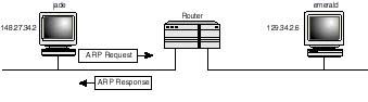
Proxy ARP Proxy ARP is an implementation of ARP at the router which is designed to handle ARP queries on behalf of hosts on remote networks. Looking at Figure 4.10, with proxy ARP on the router, then whenever jade sends out an ARP query requesting the MAC address corresponding to IP address 129.34.2.6, the following events take place:
Figure 4.18.
Proxy ARP on the router handles ARP queries on behalf of remote hosts on the network.
- 1. The ARP request broadcast is picked up by the router.
2. If the router recognizes the address as one belonging to a network which it can reach, it responds to the "ARPing" host with its own MAC address. Otherwise it discards the request silently.
3. From here, data destined to host emerald is delivered directly to the router, which in turn routes the data to emerald (how? Remember that routers route data based on the IP address embedded in the IP header, which in this case will be emerald's).
The Host-to-Host Transport Layer
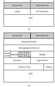
The host-to-host layer is mainly supported by two protocols: User Datagram Protocol (UDP), and Transmission Control Protocol (TCP). Whereas the former is a connectionless and unreliable protocol, the latter is a connection oriented and fully reliable protocol. Figure 20.19 shows the data structures of both protocol headers. Rather than delving deeply into the meaning of each field, this section focuses on the general features of both protocols and the use of the source and destination port numbers in both headers. The reader interested in a rigorous treatment of both protocols is referred to the book "Networking UNIX" by Sams Publishing ISBN 0-672-30584-4.
Figure 20.19.
a) Header of UDP, and b) Header of TCP transport protocol. Both protocols include
source and destination port numbers identifying the applications on whose behalf
they are exchanging data.
At the transport layer, application layer protocols are assigned port numbers. Port numbers are used in the source and destination port fields included in the transport protocol header. Transport layer protocols use them in much the same way as IP uses the protocol field. IP uses the protocol field to identify the protocol to deliver the contents of the data field to (see earlier discussion of IP header). Port numbers are used to distinguish between the applications using the services of the transport layer protocol.
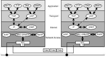
Figure 20.20 illustrates this concept. In the figure, you are shown application protocols (SMTP, FTP, DNS, and SNMP), which are engaged in the exchange of data with their respective counterparts on remote host B. Unless the transport protocol at both ends uses port numbers, it will be confusing, if not impossible, for it to deliver the data to the appropriate application protocol. As shown in the diagram, at the internet layer, IP decides where to submit the contents of data (whether to ICMP, TCP, UDP, or other) based on the protocol identifier. Assuming IP delivers the contents of the data field (which at this point consists of the user data as well as transport header) to TCP, the latter has to identify the application (FTP, TELNET, SMTP, and so on) to submit the user data to.
Figure 20.20.
While IP relies on the protocol field in its header to internally route data to one
of either TCP, UDP, or ICMP, the transport layer protocol (UDP or TCP) relies on
port numbers when routing data to the higher user protocols.
If you want to know how the port numbers are assigned, you only need to check out the contents of the file /etc/services. The details of this file are presented in the "/etc/services" section.
UDP Versus TCP UDP is a connectionless, unreliable transport protocol. This means that UDP is not sophisticated enough (as reflected in the structure of its header, see Figure 4.19) to care about the datagrams it sends down the network. Being connectionless, UDP does not negotiate a connection with its peer in the destined for the sake of establishing a control mechanism that guaranties the reliable delivery of data. Once it delivers data to IP for subsequent transmission, UDP simply forgets about it and proceeds to other business.
TCP's behavior is quite opposite to UDP's. Its sophistication allows it to deliver data reliably. TCP's sophistication stems from its ability to establish a connection with its peer on behalf of the applications engaging in the exchange of data. This allows it to successfully track the progress of the data delivery process until the process is successfully concluded. Data lost or damaged on the wire, can be easily recovered by the TCP protocol by virtue of communicating the need for retransmitting the affected data segment to its sending peer across the network.
Why use UDP then, when TCP is the more reliable of the two? To applications that are designed to handle error detection and recovery, using UDP poses no serious threat. Rather, the choice of UDP becomes the reasonable one. Equally qualifying to the use of UDP is the size and nature of data being exchanged. Transactional services involving small amounts of data behave more efficiently using UPD services than TCP. This is especially applicable to transactions in which all the data can be accommodated in one datagram. Should a datagram be lost or deformed, retransmitting that datagram incurs less overhead than is involved in establishing a TCP connection and releasing it later.
Later (refer to the "Network Troubleshooting Using UNIX Tools" section)) you will be shown how to use UNIX commands such as netstat to track transport protocol level activities.
Name Services
One way a user can establish a session with a remote host is by entering the IP address of that host as a command line parameter to the application being invoked. For example, to invoke a remote login session with a host of IP address 100.0.0.2, the following command can be entered:
# rlogin 100.0.0.2
Rather than requiring users to enter the IP address of the desired host, TCP/IP provides the means of assigning and administering names to hosts and the accompanying mechanisms responsible for resolving user-specified names to machine-usable IP addresses.
Host names are normally assigned upon system installation. To find the name assigned to your host, use the uname command with the -a option as shown here:
# uname -a
SunOS tenor 5.5.1Generic i86pc i386 i86pc
According to this output, the host name is tenor (second field from the left). To change the name of a host you can use the -S option along with the new name. To change the host name to violin, enter the following:
# uname -S violin
Beware that host name changes are not implemented in the /etc/hosts file. Consequently, whenever the name is changed using the uname command, you ought to implement the change in the /etc/hosts to ensure proper name resolution.
Host Name and the /etc/hosts Table The simplest method of resolving host names to IP addresses involves the maintenance of a host table on every UNIX system. This table is normally maintained in the /etc/hosts file. It is composed of a simple flat database in which each entry describes the IP address of a host and its associated (or assigned) name. Shown here are the contents of a sample hosts file:
#      @(#)hosts    1.2 Lachman System V STREAMS TCP  source
#      SCCS IDENTIFICATION
#      IP address    Hostname            aliases
       127.0.0.1     localhost
       100.0.0.2     jade.harmonics.com  jade
       198.53.237.1  pixel
       100.0.0.1     alto
       100.0.0.5     flyer
       100.0.0.3     tenor
As shown, each entry consists of an IP address, the host name associated with the IP address, and, optionally, an alias, where an alias is another name for the same host in question. For example, jade and jade.harmonics.com refer to the same host (that of IP address 100.0.0.2). For a user to establish a telnet session with jade, he has the choice now of entering:
$ telnet jade
or
$ telnet jade.harmonics.com
All TCP/IP applications, such as telnet and ftp, have a built-in name resolution mechanism that looks at the host's table and returns the corresponding IP address to the invoked application. The application then proceeds to contacting the corresponding host across the network. Failure to resolve the name to an IP address normally results in the error message "Unknown host".
Domain Name System The host's table-based approach to name resolution is convenient for reasonably small networks with few entries to include in the /etc/hosts file, provided that these networks are not connected to the Internet and have no need to run DNS services. Even if the network is not connected to the Internet, the idea of maintaining identical /etc/hosts files on all UNIX hosts is a time-demanding idea as it requires that changes made to one must be consistently implemented in all others. An approach that can easily become nightmarish as the size of the network increases.
Domain Name System (DNS, RFC 1035) is an alternative way to performing name resolution. Using DNS to resolve host names to IP addresses involves the use of a global, hierarchical and distributed database containing information (including IP addresses) about all hosts on the network as well as those on the Internet. The hierarchy allows for the subdivision of the name space into independently manageable partitions called domains (or subdomains). The distributed nature allows for the relocation of partitions (subdomains) of the database onto name servers belonging to sites around the network or the Internet. Consequently, sites hosting name services can be delegated the responsibility for managing their subdomains.
A name server is a host maintaining a partition of the DNS database and running a server process (on UNIX it is called named daemon) that handles name-to-IP address resolution in addition to providing some other pertinent host information.
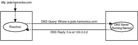
TCP/IP applications have the DNS client component, known as the name resolver, built into them. In other words, no special UNIX daemon is required to support name queries on behalf of applications. Figure 20.21 shows how a name query is handled as a user enters the ftp jade.harmonics.com to start a file transfer session. Host name jade.harmonics.com is the fully qualified domain name (FQDN) by DNS naming rules, which will be shortly discussed. According to the diagram, resolver routines, included in the ftp client, package the name in a DNS query and send it to a DNS server that the host is configured to recognize. The DNS server looks up the requested information (in the case, the IP address) and sends a reply to the requesting host.
Figure 20.21.
DNS name resolution and name servers.
Logical Organization of DNS When setting up DNS, you ought to follow certain rules in organizing your domain. Understanding those rules is as important to the proper implementation of DNS as understanding the rules which govern file system organization for the effective administration of you UNIX system.
The Internet's DNS organization will be used throughout the chapter to illustrate DNS concepts. Also, a fictitious subdomain (harmonics.com) will be introduced to illustrate some of the associated concepts at this level. It is important that you keep in mind that your situation may dictate a different organization from the Internet's. The rules and concepts, however, are still the same.
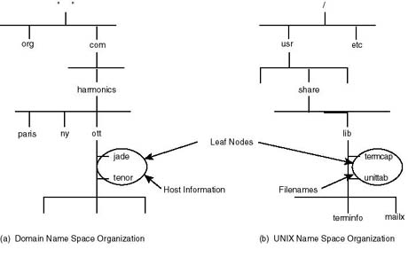
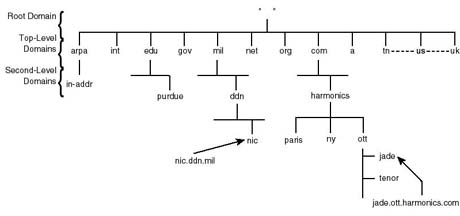
DNS is a hierarchical database of host information. Its structure resembles, to a great extent, that of computer file systems. Figure 20.22 draws an analogy between the organization of DNS and that of the UNIX file system. In both cases, the organization follows that of an inverted tree with the root at the top of the structure. Where the root of the file system is written as a slash "/", that of DNS is written as a dot "." representing the null "" character. Below the root level, the upper most domain is defined and may be subdivided into domains, which can then be further divided into subdomains--similar to dividing the UNIX file system into subdivisions called directories and subdirectories. Each subdomain is assigned a name (or a label), which can be up to 63 characters long, and can be divided further into subdomains. DNS allows nesting of up to 127 domains in one tree.
Figure 20.22.
Analogy between DNS domain and UNIX file system organization.
Each domain (or subdomain) represents a partition of the database, which may contain information about hosts in that domain, and/or information about lower domains (using the file system analogy, a directory or subdirectory represents a partition of the file system where information about both files and lower subdirectories is kept).
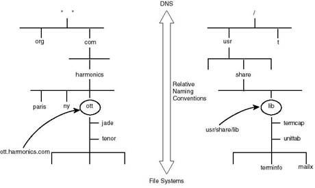
A directory, or file, under the UNIX file system, can be referred to using relative paths or an absolute path specified relative to the root. The lib directory in Figure 20.22b can be referenced relative to its parent share directory, or relative to the root "/", to become /usr/share/lib. In a similar fashion, a domain under DNS can be referred to relative to its parent domain using its name only, or relative to the root domain.
A domain name specification relative to the root is known as fully qualified domain name (FQDN). As Figure 20.23 illustrates, an absolute file or directory name is written as a sequence of relative names from the root to the target directory, or filename. Under DNS, a fully qualified domain name is written as a sequence of labels, starting with the target domain name and ending at to the root domain. For example, ott.harmonics.com is the fully qualified domain name of the subdomain ott.
Figure 20.23.
Absolute domain naming conventions compared with UNIX file system naming convention.
To translate these into real terms, you are presented with a partial portrait of the organization of the top level of the Internet's domain. The Internet authorities have divided the root level domain into top level domains, of which only the org and com domains are shown in the diagrams. While the root level domain is served by a group of root servers, top level domains are served in their turn by their own servers with each maintaining a partition of the global database.
The harmonics domain, created under the com domain, represents further subdivision of the database. This implies that Harmonics (a fictitious institute of music, with branches in Ottawa, New York, and Paris) undertook the responsibility of maintaining and administering its own name space by setting up its own authoritative server for its domain.
As shown in Figure 20.22, files represent the leaf nodes of the file system, below which no further subdivision of the name space is possible. Hosts (jade and jade) represent the leaf nodes in the domain system, and therefore the actual resource. The type of information that the leaf node might represent is quite general. For example, a leaf node may represent the IP address of the associated host, a mail exchanger (i.e. mail router) or some domain structural information.
How does a DNS server know which type of information is being queried? Each resource record stored in the database is assigned a type. When a client sends a query to a name server it must specify which type of information is requested. To be able to telnet a host for example, the client must request that the name be resolved into an IP address of a host. However, a mail application may request that the name be resolved into the IP address of a mail exchanger.
One last rule to point out: the hierarchical structure of DNS allows two or more hosts to have the same name as long as they do not belong to the same subdomain. Similarly two files may have the same filename as long as they belong to different subdirectories.
Delegation of Administrative Authority Rather than centralizing the administration of the DNS service in the hands of a single administrative authority on the Internet, DNS's hierarchical organization allows for the breakup of this responsibility into smaller manageable parts, pertaining to the administration of smaller domains of the name space. Consequently, each of the member organizations of the Internet is delegated the authority for managing its own domain. In practical terms, this requires that each of the organizations set up its own name server(s). The name server would then maintain all the host information, and respond to name queries, pertaining to that organization.
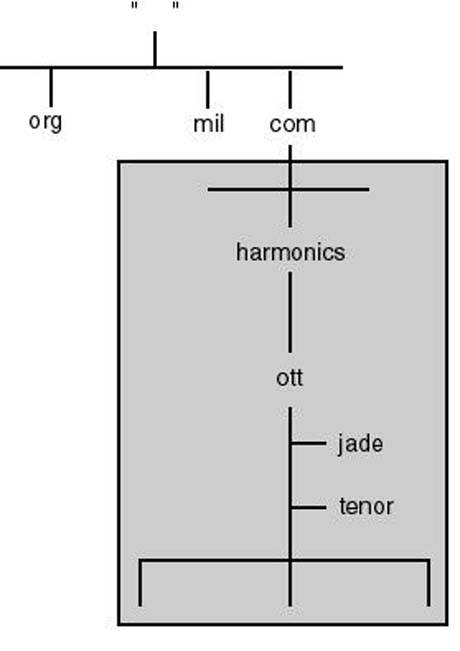
When an organization joins the Internet, it is normally delegated the responsibility of administering its own domain name space. In Figure 20.24, the responsibility of the harmonics.com domain is delegated to Harmonics (the organization).
Figure 20.24.
Domain name space delegation.
Once delegated the administration of its own domain, an organization can in turn break up its own domain into yet smaller subdomains and delegate the responsibility of administering them to other departments. Referring to the harmonics.com domain, Harmonics set up lower-level domains reflecting their geographical organization. Instead of centralizing the administration of the entire domain in the headquarters at Ottawa, the MIS department might choose to delegate the responsibility for each subdomain to local authorities at each site.
As mentioned earlier, the delegation of parts of a subdomain to member organizations or departments in practical terms translates the relocation of parts of the DNS database pertaining to those subdomains to other name servers. Hence, instead of maintaining all the information about subdomains that are delegated to other departments, the name server(s) of a the parent domain maintains pointers to subdomain servers only. This way, when queried for information about hosts in the delegated subdomains, a domain server knows where to send the query for an answer.
Delegation of administrative authority for subdomains has the following advantages:
- Distribution of workload: Relocating parts of the global DNS database to servers
belonging to member organizations considerably reduces the burden of responding to
name queries on upper and top-level DNS servers.
- Improved response time: The sharing of the query load results in improved response
time.
- Improved bandwidth utilization: Distribution of the database places servers closer to the local authority. This prevents traffic due to queries pertaining to local resources from needlessly consuming Internet bandwidth.
The Internet Top-Level Domains Many readers may have already encountered domain labels in the form of rs.internic.net, or e-mail addresses in the form of NADEEM@harmonics.com. This section attempts to familiarize you with the organization of the Internet from which those labels are derived. A kind of familiarity which is particularly important if your network is currently connected to the Internet, or if you are planning on this connection some time in the future.
The Internet DNS name space is hierarchical in organization, and follows the same rules depicted earlier. Figure 20.25 shows this hierarchical organization.
Figure 20.25.
Hierarchical organization of the Internet DNS domain name space.
As depicted in the diagram, upper levels of the Internet domain adhere to certain traditions. At the top level, the Internet started by introducing domain labels which designate organization associations. Table 20.2 provides a list of those domains and the associated affiliations.
Table 20.2. Traditional top level domains.
| Top-Level Domain | Associated Affiliation |
| com | Commercial organizations |
| edu | Educational organizations |
| gov | U.S. government organizations |
| mil | Military organizations |
| net | Networking organizations |
| org | Non-commercial organizations |
| int | International organizations |
| arpa | Special domain, for reverse resolution |
An example of an educational organization is Purdue University, which on the Internet is known as purdue.edu, whereas ibm.com represents IBM's commercial domain.
Most of the organizations joining the top level domains are located in the U.S. This is due to the fact that the Internet started as an experiment led by a U.S. agency (ARPA), in which only U.S. organizations participated. As the Internet success and popularity crossed national boundaries to become an international data highway, the top level domains were reorganized to include domain labels corresponding to individual countries. Country domain labels followed the existing ISO 3166 standard which establishes an official, two-letter code for every country in the world. In Figure 20.25, labels such as ca and tn designate Canada and Tunisia. The U.S. also has its country domain label (us) to which organizations may choose to belong instead of belonging to any of the more traditional domains.
The arpa domain (see Table 20.2) is a very special domain used by DNS name servers to reverse resolve IP addresses into their corresponding domain names.
Domains and Zones You learned earlier that once the authority for a subdomain is delegated to an organization, that organization may subdivide its domain into lower level subdomains. Subdividing a domain should not necessarily lead to delegating every subdomain's autonomy to other member departments in the organization. So although a domain is partitioned into many lower-level domains, authority over the domain can be aligned along zone boundaries, in which case a zone may contain a subset of the domains that the parent domain contains.
Figure 20.26 illustrates the difference between a domain and a zone. As show in the figure, harmonics domain contains the ott, ny, and paris subdomains. Yet, only two zones of authority are established: the harmonics zone which includes both ott and paris subdomains, and the ny zone including to the ny domain. When setting up name servers, you will be assigning zones of authority--you will be configuring them to maintain complete information about the zone for which they are said to have authority. You can, if you wish, make a name server authoritative for more than one zone.
Figure 20.26.
Domains and zones.
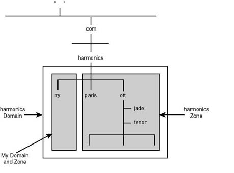
Authority for the harmonics domain is reduced to two zones: the harmonics zone, which contains information about both ott and paris subdomains, and the ny zone, which contains information about the ny domain only.
Name Servers Setting up DNS services to support the domain or zone for which an organization is delegated authority involves creating a set of authoritative servers for that zone. At a minimum, two servers a primary and secondary should be setup.
The primary name server is where the database files are being maintained and is the most time consuming to setup. Changes made to the DNS whether to the layout or structure of the domain being delegated or simple updates to the database must be administered and reflected on the primary name server. For example, to add a new host to the network, you have to assign it both a name and an IP address, and you must enter those assignments in the DNS database contained on the primary server.
The secondary name server is easier to set up than the primary. It is different from the primary in that it derives its database from the primary's by virtue of replicating it through a process known as zonal transfer. Once set up, the secondary requires very little maintenance.
Every time the secondary server is rebooted, it undergoes the zonal transfer process by contacting the primary server for the zone for which they both are responsible, and requesting all the information pertaining to that zone. Thereafter, the secondary server routinely polls the primary server for any updates that might have been made to the database. As will be shown under the section "Implementing DNS," a secondary server can be easily configured to backup the zone data after transfer to disk files. This option allows the secondary server to reload its data using the backup files instead of undergoing zonal transfer every time the server is restarted--resulting in reduction in bandwidth consumption due to zonal transfers, and the better availability of data in case the secondary fails to hear for the primary when the transfer is initiated.
It is not absolutely necessary to install any other than the primary server in order to bring up the DNS service. Including a secondary server has, however, the following advantages:
- Redundancy: there is no difference between a primary and secondary server
except for the source of information that each relies on in responding to name queries.
Both servers are equally capable to responding to such queries. Consequently, with
the presence of a secondary server, should one of them accidentally stop responding
to user queries, one will be capable of taking over, provided that user workstations
are setup to contact both servers for queries.
- Distribution of workload: Because both servers are equally capable to
responding to all types of queries, the environment can be setup so that the workload
on these servers is fairly shared. The added benefit of sharing the workload is improved
response time.
- Physical proximity: by having more than one server, you will be able to strategically locate each one of them so they are where they're needed most. Thus cutting on response time.
Name Service Resolution Process Whenever a name server is queried by a client, it is mandatory that the server responds with a valid answer regardless of whether the query pertains to the domain for which the server is authoritative or not. Queries pertaining to other domains, on the local network, or around the Internet should be forwarded to other servers for a response. To query name servers on behalf of the client, every name server must maintain pointers (that is, entries including the IP addresses) to the root servers. Root servers in turn must maintain data about all top-level domain, and so on. The process of querying other servers on behalf of a client is commonly known as a resolution referral process.
Figure 20.27 illustrates the resolution referral process. In the diagram, a DNS server (somewhere in the Internet universe) receives a name query from a client. The query requests the IP address of host oboe.ny.harmonics.com.. Assuming that the server does not know the answer, rather than responding to the client with a negative response, it sends the query to a root server. The root server determines from the host name that it falls under the com domain. Consequently, it responds to the originating server with the address list of the com domain servers. The local server treats the response as referral to the com servers, at which point it redirects the query to one of these servers. In its turn, the com server determines that the queried object falls under the harmonics subdomain's authority and therefore refers the local server to contact the subdomain's server, which in turn finally refers it to the server of ny.harmonics.com for answer.
Figure 20.27.
Name resolution referral process.
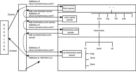
Caching In order to save bandwidth and improve the response time it takes to answer a query, DNS defines a caching mechanism that allows name servers (of all types) to cache response data for future reference. In the example of Figure 20.27, the local name server caches the IP address-to-host name association of oboe.ny.harmonics.com after responding successfully to the client's query. This way, if queried for the same host (oboe.ny.harmonics.com), the server will be able to respond directly from its cache instead of undergoing the time consuming resolution referral process all over.
Name servers do not just cache data pertaining to the query in effect. Rather, they cache all the data they discover in the process of responding to that query. For example, the local server in Figure 20.27 would cache all the referral data that led to the response to the query pertaining to host oboe.ny.harmonics.com. The referral data includes names and IP addresses of the servers that are authoritative for the root-level, com, and harmonic domains. Caching referral data cuts on the time that the referral process takes. In the event, for example, the name server is queried for host fake.somewhere.com, it does not have to start the referral process from the root level if it already has in its cache the necessary information to go directly to a com domain server for referral; thus cutting on the number of referral steps by one in this case.
To avoid having a name server continue using cached data after it has expired (due to changes made to that data on authoritative name servers), DNS defines a time-to-live (TTL) configuration parameter for that data. After expiration of the specified TTL time, the server must discard the data in its cache and request an update from authoritative name server.
Reverse Resolution of Pointer Queries Figure 20.28 shows a partial portrait of the organization of the Internet's global DNS service. Of particular interest is the in-addr.arpa reverse resolution domain. Called as such because it is used to reverse resolve an IP address to its fully qualified domain name.
Reverse resolution is particularly useful for security. Some of the remote access services, such as rlogin and remote copy (rcp), are only accessible if the hosts from which users are attempting access are privileged to doing so. A host supporting such services normally maintains the names (not the IP addresses) of the other hosts allowed access in special files (such as $HOME/.rhosts and /etc/hosts.equiv ). Upon receiving a request for remote access service, a secure server issues a query to the name server requesting reverse resolving the address to its domain name for subsequent verification for eligibility to the service.
The in-addr.arpa domain is designed to provide an efficient mechanism for responding to queries requesting reverse resolution. As shown in Figure 20.28, in-addr.arpa is simply another domain that uses IP addresses for subdomain names. The in-addr.arpa domain itself is organized into 256 domains, one corresponding to each possible value of the first byte of the IP address. Similarly, below each of those domains, there can be up to 256 subdomains corresponding to the second byte of the IP address, and so on, until the entire address space is represented in the in-addr.arpa domain.
Figure 20.28.
Organization of the in-addr.arp domain.
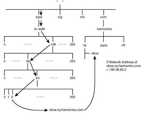
Whenever an organization joins the Internet, it is delegated the responsibility to administer two or more domains. These are the official domains that it registered under. For example, in the case of Harmonics, Inc. it is the harmonics.com domain, and the in-addr.arpa domain that corresponds to the address range that it has been assigned by the appropriate Internet authority. If, for example, Harmonics Inc. was assigned the Class C pool of addresses 198.58.63.0, then it is delegated the authority for managing the 63.58.198.in-addr.arpa domain. Notice how the IP address portion of the reverse domain is spelled backwards. This is in compliance with the DNS naming rules that were discussed earlier. For example, if the IP address of oboe.ny.harmonics.com is 198.58.63.2, its in-addr.arpa domain label becomes 2.63.58.198.in-addr.arpa, again in conformance with the way fully qualified domain names should be referenced.
Assuming that a host receives a remote login request from host address 198.58.63.2, the receiving host authenticates the request by sending out a query for reverse resolution (officially known as a pointer query type) to its local name server. The local name server then must find the domain names corresponding to the specified host IP address by undergoing the same resolution referral process, that was outlined earlier, starting at 198.in-addr.arpa level and moving downward the tree until it successfully reaches the domain label 2.63.58.in-addr.arpa, which is then fetched for the corresponding host domain label (oboe.ny.harmonics.com). The name is then returned to the remote access server for use in verifying access privileges.
Configuring UNIX for TCP/IP
This section is devoted to detailing the set up process from the preparation phase to the actual implementation phase. Throughout, the discussion mainly addresses the "how to" process on UNIX SVR4 hosts. Whenever necessary differences with other variants of UNIX will be highlighted.
Preparing to Set Up and Configure TCP/IP
Setting up and configuring TCP/IP on UNIX hosts is a fairly simple and straightforward matter provided that you have done a little bit of up front preparation. Most of the preparation has to do with defining the parameters that are critical to the successful completion of the task of setting up the host for connection to the common network. Following are the points to consider when undertaking such a task:
- Number of network interfaces: a host might be required to have more than
one network interface card in order to attach the more than one network. This is
typically desired when the host is setup to route traffic between those networks
or to behave as a security firewall.
- Network interface labels: UNIX vendors refer to network interfaces using
labels. Each make is labeled uniquely from others. For example, on a Solaris 2.x
system, a 3Com Etherlink III (3C5x9) interface is referred to, or labeled, as elx.
The first interface of its kind is labeled elx0, the second as elx1, and so on. Before
proceeding to configuring the interfaces using the applicable parameters (such as
IP address, netmask,É) make sure you know what the interface label(s) are.
- hostname: Each host must be assigned a host name. Typically, the host name is the name set during system installation. Finding out what the host name is, is a simple matter of entering the "uname -n" command as shown here:
# uname -n
tenor
- Bear in mind however, that the name assigned to the host during installation may not be suitable to use on the network. One obvious cause would be name collision--that is the possibility of two computers having the same name. Another reason is the potential conflict with official host naming rules that are in force in your environment. Should the requirement arise for changing the name, use the uname command with the -S option as shown here:
# uname -S newname
- where newname is the new host's name.
In the case of configuring the host for supporting more than one network interface, you ought to assign it one name per interface. You cannot have the same name associated with all supported interfaces. Consequently, have all the names ready for the time of implementation.
- Domain name: If you have domain name service installed on your network,
you must decide where in the domain hierarchy does the host belong and note the corresponding
complete domain name of that host. For example if host tenor is said to belong to
ny.harmonics.com, its full domain name becomes tenor.ny.harmonics.com.
- IP addresses assigned to the network interfaces: Each of the network interfaces
must be assigned a unique IP address. Have the addresses ready in dotted decimal
notation.
- Subnet masks: determine and note the applicable subnet mask if the default
is not acceptable. The mask can be entered, when required in the setup process, using
dotted decimal or hexadecimal notation.
- IP addresses of domain name servers: if domain name service is installed
on the network, you ought to have the addresses of at least the primary and one secondary
name servers. These addresses will be required in the process of setting up the DNS
resolver on the UNIX host.
- IP address of the default gateway(that is, default router): On a routed network (a network connected to other networks) every host must be configured to recognize a default router--hence the need for the IP address of the router.
The above completes the list of the minimal requirements for the graceful implementation of TCP/IP on UNIX hosts. There are situations where configuring hosts may require additional information. Additional information can, however, always be implemented after all the above parameters are taken care of and the network setup is verified to work satisfactorily.
TCP/IP Setup Files
Installing and configuring TCP/IP involves several files that you are required to be aware of. Each of the files depicted below takes care of a certain aspect of the TCP/IP services rendered by the UNIX host.
/etc/hosts The /etc/hosts file is where the host names to IP address associations are maintained. The following is an example of an /etc/hosts file as it is on host jade (see Figure 20.29):
#
# Internet host table
#
# IP address    hostname    aliases
#
127.0.0.1    localhost
100.0.0.2    jade
198.53.237.1    jade1            # jade's second interface
100.0.0.3    tenor              nfsserver # is my nfs server
100.0.0.5    alto        # my gateway to the internet
Figure 20.29.
Host jade connects to and routes data between two networks: 100.0.0.0
and 198.53.237.0.
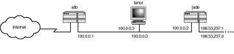
Text following the # character is ignored, and is meant to include comments and documentation. As shown above, every file entry consists of an IP address, the corresponding hostname, and optional aliases. Three entries in this file pertaining to host jade are of particular interest:
- An entry which maps the 127.0.0.1 to localhost. This entry corresponds to the loopback interface. It is absolutely necessary that each system has an identical entry in its /etc/hosts file. The loopback address allows for the local testing of the various components of TCP/IP without introducing traffic (due to these tests) on the wire. For example, you can establish a local ftp session by entering the following command:
# ftp localhost
- In this particular situation, the sanity of FTP service can be tested and established
without needing another to establish a session with the host in question.
- An entry which maps 100.0.0.2 to the host's network node name jade.
- An entry which maps IP address 198.53.237.1 to jade1, a host name assigned to another network interface card supported by TCP/IP in this host. As shown in Figure 20.29 jade connects to two networks 100.0.0.0 and 198.53.237.0.
Notice how tenor is also assigned an alias, nfsserver. An alias is just another name which you can use to refer to the same host or interface. Because tenor supports NFS services for the rest of the network, it was conveniently aliased as nfsserver. Consequently, the network administrator and users will be able to reference the host either by its name or its alias.
/etc/hosts also includes IP address to name mappings pertaining to other hosts (e.g. alto). If you do not have DNS installed on your network, the /etc/hosts file may have be updated whenever a new host is set up on the network, or an existing one is reconfigured to a different IP address.
/etc/networks The /etc/networks file is similar to the /etc/hosts file in function. Instead of host names, /etc/networks contains network names to network IP address associations. Optionally, aliases can be included. Names included in this file normally pertain to known networks which comprise the Internet. Following is an example /etc/networks file:
# Name        Network Number

att                 12
xerox-net           13
hp-internet         15
dec-internet        16
milnet              26
ucdla-net           31
nextdoor-net        198.53.237
loopback-net        127
The /etc/networks file allows you to refer to networks, local or on the Internet, by name when, for example, configuring the routing table on the host as shown here:
# route add nextdoor-net 100.0.0.1 1
add net nextdoor-net: gateway 100.0.0.1
/etc/services As discussed earlier, each of the TCP/IP application layer services, such as FTP, TELNET, and RLOGIN, are assigned port numbers at the transport layer. The /etc/services database contains the information which maps every recognized service protocol to a static port number, also known as a well known port number. An application uses a uniquely assigned port number to identify itself to the transport provider (at the host-to-host layer) and to remote peers across the network.
Following is a partial list of well recognized services as documented in RFC 1060. Every entry in this list consists of the service name and its associated port number/transport protocol provider. Some services run over both TCP and UDP (e.g. daytime service). In such a case the service is listed twice, once for TCP and once for UDP.
RFC 1060
In addition to assigned port numbers, RFC 1060 contains a complete listing of other categories of assigned numbers including (but not limited to) protocol numbers, UNIX assigned ports, and Ethernet assigned address blocks. It might prove useful to downloading and maintaining a copy of this RFC. This RFC, as well as all others referenced in the book, are available from the ds.internic.net Internet site.
/etc/services database file is created during TCP/IP installation. The only time you have to worry about it is when installing a new application/service. In this case you will have to edit the file to include an entry as directed by the application vendor. You may find the file a useful reference when troubleshooting the network.
#
#    assigned numbers from rfc1060
#

#service    port/transport
tcpmux    1/tcp
echo        7/tcp
echo        7/udp
discard    9/tcp        sink null
discard    9/udp        sink null
systat        11/tcp        users
systat        11/udp    users
daytime    13/tcp
daytime    13/udp
netstat        15/tcp
netstat        15/udp
qotd        17/tcp        quote
qotd        17/udp    quote
ftp-data    20/tcp
ftp        21/tcp
telnet        23/tcp
smtp        25/tcp        mail
time        37/tcp        timserver
time        37/udp    timserver
name        42/tcp        nameserver
name        42/udp    nameserver
whois        43/tcp        nicname        # usually to sri-nic
whois        43/udp    nicname        # usually to sri-nic
nameserver    53/udp    domain
nameserver    53/tcp        domain
apts        57/tcp                    #any private terminal service
apfs        59/tcp                    #any private file service
bootps        67/udp    bootp
bootpc        68/udp
tftp        69/udp
rje        77/tcp        netrjs            #any private rje
finger        79/tcp
link        87/tcp        ttylink
supdup    95/tcp
hostnames    101/tcp    hostname        # usually to sri-nic
sunrpc        111/udp    rpcbind
sunrpc        111/tcp    rpcbind
auth        113/tcp    authentication
sftp        115/tcp
uucp-path    117/tcp
nntp        119/tcp    usenet readnews untp # Network News Transfer
eprc        121/udp
ntp        123/tcp                # Network Time Protocol
ntp        123/udp                # Network Time Protocol
NeWS        144/tcp    news            # Window System
iso-tp0        146/tcp
iso-ip        147/tcp
bftp        152/tcp
snmp        161/udp
snmp-trap    162/udp
cmip-manage    163/tcp
cmip-agent    164/tcp
print-srv    170/tcp
#
# UNIX specific services
#
# these are NOT officially assigned
#
exec        512/tcp
login        513/tcp
shell        514/tcp    cmd            # no passwords used
printer        515/tcp    spooler        # line printer spooler
timed        525/udp    timeserver
courier    530/tcp    rpc            # experimental
/etc/protocols Recall that the IP header (see Figure 20.6) includes a PROTOCOL field. This field contains a number which uniquely identifies the IP protocol service user. Similar in functionality to transport port numbers, protocol numbers help IP with internally routing data to their respective user protocols. /etc/protocols is created in your system during TCP/IP installation and should require no change. An example file listing follows:
#
# Internet (IP) protocols
#
ip    0    IP    # internet protocol, pseudo protocol number
icmp    1    ICMP    # internet control message protocol
ggp    3    GGP    # gateway-gateway protocol
tcp    6    TCP    # transmission control protocol
egp    8    EGP    # exterior gateway protocol
pup    12    PUP    # PARC universal packet protocol
udp    17    UDP    # user datagram protocol
hmp    20    HMP    # host monitoring protocol
xns-idp    22    XNS-IDP    # Xerox NS IDP
rdp        27    RDP    # "reliable datagram" protocol
The /etc/protocols file is created and initialized during system installation. As an administrator, you will hardly have to change or update its contents. However you shouldn't attempt to delete this file or tamper with its contents as it is referenced by TCP/IP daemons every time the system is brought up.
/etc/ethers Unlike the files discussed above, /etc/ethers is not created by the system during TCP/IP installation. If you are planning on providing RARP or BOOTPD services, you need to create this file. RARP uses this file to map Ethernet addresses to IP addresses. An example of an /etc/ethers file follows:
#
# MAC to hostname mappings
#
# ether_mac_addr.    hostname    comments
#
00:00:c0:9e:41:26    violin        #strings dep't
02:60:8c:15:ad:18    bass
Rather than including IP addresses, the /etc/ethers file contains host names. Upon cross-referencing this file with /etc/hosts any MAC address can be easily mapped to its IP address. This means that unless both /etc/hosts and /etc/ethers are consistently maintained some users may end up having difficulties acquiring an IP address, and consequently connecting to the network at boot time.
/etc/netmasks The /etc/netmasks file associates network IP addresses with network addresses. You need to create and maintain this file if you are planning on subnetting your network. Here is a sample netmasks file:
#
#Network subnet masks
#
#Unless your network is subnetted, do not bother to maintain this file
#
#Network        subnet mask
134.54.0.0        255.255.255.0
167.12.0.0        255.255.192.0
138.52.0.0         255.255.255.0
For each network that is subnetted, a single line should exist in this file with the network number, and the network mask to use on that network. Network numbers and masks may be specified in the conventional dotted decimal notation. For example,
138.52.0.0 255.255.255.0
specifies that the Class B network 128.32.0.0 should have eight bits of subnet field and eight bits of host field, in addition to the standard sixteen bits in the network field.
/etc/hosts.equiv /etc/hosts.equiv contains the names of trusted hosts. Users logging in to the system from a trusted host using any or the r-utilities (see the section "Well-known Services") are not required to supply a password, provided that they already have a valid login id in the /etc/passwd file on the target host. The following listing provides an example of /etc/hosts.equiv:
#
# Trusted hosts
#
jade
tenor
alto
soprano
Users on jade, tenor, alto, and soprano can log in to the system on which the listed file is maintained, without supplying a password, provided they are in the /etc/passwd database of that system.
~/.rhosts .rhosts must be created in the user's remote home directory. It allows or denies access to that specific user. In its simplest form, the ~/.rhosts file looks like the following one:
#
#$HOME/.rhosts file
#
jade
tenor
The above entries mean that the user, in whose remote home directory .rhosts is created, can log in from jade and tenor without supplying a password.
/etc/inet Directory In this directory the configuration file inetd.conf is maintained. This file dictates the behavior of the superserver inetd daemon. The superserver daemon's responsibility is to invoke and control application protocol daemons whenever the need arises. Examples of applications daemons that are supervised and controlled the inetd daemon are the ftpd and telnetd (that is the FTP and TELNET server daemons).
Some SVR4 systems maintain the hosts, protocols, and services databases, discussed earlier, in /etc/init and maintain symbolic links to /etc/hosts, /etc/protocols, and /etc/services.
/etc/inet/inetd.conf Rather than allowing every service daemon to listen to requests on its own port, UNIX developers chose to delegate the responsibility of listening to requests on behalf of all service daemons to one server (also known as superserver) called inetd. In doing so the demand on system resources is significantly reduced. Only when the superserver detects a service request it will invoke the daemon to which the service pertains. The /etc/inet/inetd.conf configuration file allows inetd to determine, upon startup, the daemons on whose behalf to listen to service requests. Unless a service daemon is enabled through the inetd.conf file, service requests pertaining to that daemon will be discarded by the inetd daemon. More details on inetd and inetd.conf are provided later in the chapter.
Startup of TCP/IP
Different variants of UNIX have different implementations of the TCP/IP startup process and associated scripts. In particular, three implementations are presented in this section; these are:
- TCP/IP Startup on SVR4
- TCP/IP Startup on Solaris 2.x
- TCP/IP Startup on BSD
TCP/IP Startup on SVR4 TCP/IP is started at boot time when run level 2 (multiuser run level) is entered by the /etc/init.d/inetinit script. This script sets out by configuring, linking and loading various STREAMS modules and drivers that are required for the STREAMS TCP/IP protocol stack. If STREAMS is loaded successfully, inetinit executes the /etc/confnet.d/inet/config.boot.sh to configure all of the supported network interfaces as defined in the /etc/confnet.d/inet/interface file (see note below for a sample listing of its contents). Following is a listing of the contents of inetinit script:
#      @(#)inetinit    1.4 STREAMWare TCP/IP SVR4.2  source
#      SCCS IDENTIFICATION
#ident    "@(#)cmd-inet:common/cmd/cmd-inet/etc/init.d/inetinit    1.9.7.7"

#    inet startup

LOG=/tmp/inet.start
PermLog=/var/adm/log/inet.start
export LOG PermLog
exitcode=0

SLINK=/usr/sbin/slink
IFCONFIG=/usr/sbin/ifconfig
STRCF=/etc/inet/strcf
MSG1="\nTCP/IP startup was not entirely successful. Error messages in $LOG"
DATADIR=/etc/confnet.d/inet
DATASCRIPT=$DATADIR/config.boot.sh
DATABASE=$DATADIR/interface
NUstrcf=$DATADIR/strcf.custom
UPSAVE=$DATADIR/up.save     # ifconfig commands built for "up" operation
KLUDGE=kludge

export DATADIR DATASCRIPT DATABASE NUstrcf
#
# construct the commands to set-up and take-down the protocol stack.
#
UP="$SLINK -v -c $NUstrcf $KLUDGE"
DOWN="$SLINK -u -c $NUstrcf $KLUDGE"

case "$1" in
start)
    #the LOOP=up or LOOP=down portion of code is to determine
    #if we are running this 'start)' code following running
    #the 'stop)' code.  Once we've run an ifconfig lo0 {address},
    #ifconfig lo0 will not have a non-zero return code, even after
    #unlinking the transport stack.
    #So use the loopback transport UP|DOWN as a flag for the
    #boot code.
    ifout="'ifconfig lo0 2>/dev/null'"
    ifret=$?
    case X"$ifout" in
        Xlo0*flags=*\<UP,*)
            LOOP=up ;;
        *)    LOOP=down ;;
    esac

    if [ $ifret != 0 -o $LOOP != up ]
    then
        #
        # the network stack is not yet up (at least there is
        # no loopback), "make" the strcf and ifconfig commands
        # (ie, iff any dependency changed).
        #
        cmd="$DATASCRIPT up"
        echo "The following commands ran from /etc/init.d/inetinit"
        echo \
"The following commands were run by the boot time configuration
script, $DATASCRIPT, by running
$cmd
"

        eval "$cmd"
        if [ $? -ne 0 ]
        then
            exitcode=1
        fi

        echo "$UP"
        if    $UP
        then
            if [ -f "$UPSAVE" ]
            then
                #
                # issue all the ifconfig commands
                #
                echo "Commands from $UPSAVE:"
                cat $UPSAVE
                echo
                . $UPSAVE
            fi
        else
            #
            # failed to build the stream stack so try to
            # unbuild it.
            #
            $DOWN >/dev/null 2>&1
            echo "$MSG1" >&2
            exit 1
        fi
        if [ -x /usr/eac/bin/initsock ]
        then
            /usr/eac/bin/initsock
        fi
    fi > $LOG 2>&1

    rm -f $LOG $PermLog

    # run startup script
    /bin/sh /etc/inet/rc.inet start
    if [ $? -ne 0 ]
    then
        exitcode=1
    fi
    exit $exitcode

    ;;

stop)
    #
    # rc0 and rc1 take care of killing when going down to states 0,1,5,6
    #
    set 'who -r'
    if [ "$3" = "2" -o "$3" = "3" ]
    then
    #
    # kill the various standalone daemons
    #
        kill -9 '/usr/bin/ps -e \
        | /usr/bin/awk '/in\.routed/ || /in\.gated/ || /in\.xntpd/ \
        || /in\.timed/ || /in\.named/ || /in\.pppd/ || /in\.snmpd/ \
        { print $1}'' 2>/dev/null

    fi
    #
    # bring down the protocol stack
    # use the strcf script compiled on the way up even if there
    # were changes made.  Those changes will go into effect
    # the next time it comes up.
    #
    $IFCONFIG -a down >/dev/null 2>&1
    if [ -f $NUstrcf ]
    then
        $DOWN >/dev/null 2>&1
    fi
    exit 0
    #the LOOP=up or LOOP=down portion of the 'start)' code is
    #checking to see if it is following the above 'stop)' code.
    #Once we've run an ifconfig lo0 {address},
    #ifconfig lo0 will not have a non-zero return code, even after
    #unlinking the transport stack.
    ;;

*)
    exit 1
esac
NOTE: The following is an example of the contents of the /etc/confnet.d/inet/interface:lo:0:localhost:/dev/loop::add_loop: ne2k:0::/dev/ne2k_0:-trailers:: el3:0:orbit:/dev/el3_0:-trailers::According to this listing, two network interfaces are supported. These are ne2k and el3 corresponding to the NE2000 and 3C509 network cards. The first entry (lo) pertains to the loopback interface. Each entry is made of colon delimited fields. Entries in the interface file have the following format:
prefix:unit#:addr:device:ifconfig_opts:slink_opts:where,
prefix is used by the ifconfig or netstat commands to configure the interface, or to gather its statistics.
unit # refers to the unit number (instance number) of that interface.
addr should contain either the IP address assigned to the interface, or an existing hostname in the /etc/hosts file. If null string is included instead, as in the second entry, then null will be expanded to '/usr/bin/uname -n' and the interface will be configured to the IP address of the corresponding network node name of the system.
device refers to the node name of the transport provider. This field is used by slink (i.e STREAMS link) command for the configuration and installation of the protocol stack onto the STREAM head.
ifconfig_opts is normally made to contain options that are supported by the ifconfig command. One common option is the -trailers (discussed later in the chapter) option.
slink_opts is used by slink to initialize the device into the TCP/IP protocol stack. A null field allows for customization.
Once control is transferred to config.boot.sh (not listed due to its length), it loops through all of the interfaces specified in the /etc/confnet.d/inet/interface file, including the loopback interface, configuring each using ifconfig to the proper IP address, netmask, and broadcast address. It also uses slink command to configure and load the protocol stack onto the STREAMS head for each interface device.
If the network interfaces are successfully configured and brought up, /etc/init.d/inetinit runs the /etc/inet/rc.inet script.
NOTE: A final remark on the inetinit script is that it is used for both starting as well as stopping TCP/IP services. It starts TCP/IP when the system is brought to the multi-user level and stops TCP/IP when the system is shutdown or brought down to single user level. This is normally accomplished by linking /etc/init.d/inetinit to /etc/rc2.d/S69inet, which is run along with all the other scripts that begin with S in that directory.
/etc/inet/rc.inet The contents of the rc.inet script are listed below. As can be seen from the listing, rc.inet starts TCP/IP daemons which have been verified as properly configured. Taking in.named, the domain name service daemon, as an example, rc.inet checks in the /etc/inet directory for the corresponding boot configuration file (named.boot). If named.boot is found, the daemon is invoked.
#      @(#)rc.inet    1.5 STREAMWare TCP/IP SVR4.2  source
#      SCCS IDENTIFICATION
#ident    "@(#)cmd-inet:common/cmd/cmd-inet/etc/inet/rc.inet    1.3.8.7"

# Inet startup script run from /etc/init.d/inetinit
LOG=/tmp/inet.start
PermLog=/var/adm/log/inet.start
export LOG PermLog
exitcode=0

# Label the error log
echo "The following commands were run from /etc/inet/rc.inet" > $LOG
#
# Add lines here to set up routes to gateways, start other daemons, etc.
#
#
# Run the ppp daemon if /etc/inet/ppphosts is present
#
if [ -f /etc/inet/ppphosts -a -x /usr/sbin/in.pppd ]
then
    /usr/sbin/in.pppd
fi
# This runs in.gated if its configuration file (/etc/inet/gated.conf) is
# present.  Otherwise, in.routed is run.
#
if [ -f /etc/inet/gated.conf -a -x /usr/sbin/in.gated ]
then
    /usr/sbin/in.gated
else
    #
    # if running, kill the route demon
    #
    kill 'ps -ef|grep in[.]routed|awk '{print $2}'' 2>/dev/null
    /usr/sbin/in.routed -q
fi
#
# /usr/sbin/route add default your_nearest_gateway hops_to_gateway
# if [ $? -ne 0 ]
# then
#    exitcode=1
# fi

#
#  Run the DNS server if a configuration file is present
#
if [ -f /etc/inet/named.boot -a -x /usr/sbin/in.named ]
then
    /usr/sbin/in.named
fi

#
#  Run the NTP server if a configuration file is present
#
if [ -f /etc/inet/ntp.conf -a -x /usr/sbin/in.xntpd ]
then
    /usr/sbin/in.xntpd
fi
#
# return status to /etc/init.d/inetinit
There are situations in which you have to make changes to this file. For example to install static routes at boot time, you need to edit the rc.init file to include as many route add commands as may be required to support those routes including support for the default gateway. Also, you may need to change the file path specifications of configuration files pertaining to some daemons such as in.named.
The startup process completes with the invocation of the superserver daemon inetd. As shown in a later section, inetd is responsible for invoking (on demand) and controlling many of the TCP/IP application service daemons such as ftpd, and telnetd.
TCP/IP Startup on Solaris 2.x Although Solaris 2.x is a UNIX SVR4 operating system, it does not follow the startup procedures depicted above. Solaris 2.x relies on three scripts for bringing up TCP/IP services. These are:
- /etc/init.d/rootusr
- /etc/init.d/inetinit
- /etc/init.d/inetsrv
/etc/init.d/rootusr Considering that some workstations rely on remote file systems resources (in particular /usr) to function properly, this script's primary function is to configure enough of TCP/IP interfaces and services that are necessary to mount (using Network File System - that is, NFS) these resources. Here is the code listing for this script:
#!/sbin/sh
# Make sure that the libraries essential
# to this stage of booting can be found.
LD_LIBRARY_PATH=/etc/lib; export LD_LIBRARY_PATH

#
#
# Configure the software loopback driver. The network initialization is
# done early to support diskless and dataless configurations.
#
/sbin/ifconfig lo0 127.0.0.1 up 2>&1 >/dev/null

#
# For interfaces that were configured by the kernel (e.g. those on diskless
# machines), reset the netmask using the local "/etc/netmasks" file, if
# one exists.
#
/sbin/ifconfig -au netmask + broadcast + 2>&1 >/dev/null

#
# Get the list of network interfaces to configure by breaking
# /etc/hostname.* into separate args by using "." as a shell separator
# character, then step through args and ifconfig every other arg.
# Set the netmask along the way using local "/etc/netmasks" file.
# This also sets up the streams plumbing for the interface.
# With an empty /etc/hostname.* file this only sets up the streams plumbing
# allowing the ifconfig auto-revarp command will attempt to set the address.
#
interface_names="'echo /etc/hostname.*[0-9]        2>/dev/null'"
if test "$interface_names" != "/etc/hostname.*[0-9]"
then
        (
        echo "configuring network interfaces:\c"
                IFS="$IFS."
                set 'echo /etc/hostname\.*[0-9]'
                while test $# -ge 2
                do
                        shift
                        if [ "$1" != "xx0" ]; then
                 addr='shcat /etc/hostname\.$1'
                 /sbin/ifconfig $1 plumb
                 if test -n "$addr"
                 then
                    /sbin/ifconfig $1 inet "$addr" netmask + \
                        broadcast + -trailers up \
                        2>&1 > /dev/null
                 fi
                 echo " $1\c"
                        fi
                        shift
                done
        echo "."
        )
fi

#
# configure the rest of the interfaces automatically, quietly.
#
/sbin/ifconfig -ad auto-revarp netmask + broadcast + -trailers up \
    2>&1 >/dev/null

#
# Set the hostname from a local config file, if one exists.
#
hostname="'shcat /etc/nodename        2>/dev/null'"
if [ ! -z "$hostname" ]; \
then
        /sbin/uname -S $hostname
fi

#
# Otherwise, set host information from bootparams RPC protocol.
#
if [ -z "'/sbin/uname -n'" ]; then
        /sbin/hostconfig -p bootparams
fi

#
# If local and network configuration failed, re-try network
# configuration until we get an answer.  We want this loop to be
# interruptible so that the machine can still be brought up manually
# when the servers are not cooperating.
#

trap 'intr=1' 2 3
while [ -z "'/sbin/uname -n'" -a ! -f /etc/.UNCONFIGURED  -a -z "${intr}" ]; do
        echo "re-trying host configuration..."
        /sbin/ifconfig -ad auto-revarp up 2>&1 >/dev/null
        /sbin/hostconfig -p bootparams 2>&1 >/dev/null
done
trap 2 3

echo "Hostname: '/sbin/uname -n'" >&2

#
# If "/usr" is going to be NFS mounted from a host on a different
# network, we must have a routing table entry before the mount is
# attempted.  One may be added by the diskless kernel or by the
# "hostconfig" program above.  Setting a default router here is a problem
# because the default system configuration does not include the
# "route" program in "/sbin".  Thus we only try to add a default route
# at this point if someone managed to place a static version of "route" into
# "/sbin".  Otherwise, we may add the route at run level 2 after "/usr"
# has been mounted and NIS is running.
#
# Note that since NIS is not running at this point, the router's name
# must be in "/etc/hosts" or its numeric IP address must be used in the file.
#
if [ -f /sbin/route -a -f /etc/defaultrouter ]; then
        /sbin/route -f add default 'cat /etc/defaultrouter' 1
fi

#
# Root is already mounted (by the kernel), but still needs to be checked,
# possibly remounted and entered into mnttab. First mount /usr read only
# if it is a separate file system. This must be done first to allow
# utilities such as fsck and setmnt to reside on /usr minimizing the space
# required by the root file system.
#
exec < ${vfstab}; readvfstab "/usr"
if [ "${mountp}" ]
then
    if [ "${fstype}" = "cachefs" ]; then
        #
        # Mount without the cache initially.  We'll enable it
        # later at remount time.  This lets us avoid
        # teaching the statically linked mount program about
        # cachefs.  Here we determine the backfstype.
        # This is not pretty, but we have no tools for parsing
        # the option string until we get /usr mounted...
        #
        case "$mntopts" in
        *backfstype=nfs*)
            cfsbacktype=nfs
            ;;
        *backfstype=hsfs*)
            cfsbacktype=hsfs
            ;;
        *)
            echo "invalid vfstab entry for /usr"
            cfsbacktype=nfs
            ;;
        esac
        /sbin/mount -m -F ${cfsbacktype} -o ro ${special} ${mountp}
    else
        /sbin/mount -m -o ro /usr
    fi
fi
As shown, the script sets out by configuring the local loop interface (that is, IP address 127.0.0.1) then proceeds to configuring all the network card interfaces that are installed in the system. Rather than relying on a common configuration file where all the supported network interfaces are defined, such as the /etc/confnet.d/inet/interfaces (which is commonly used on UNIX SVR4 systems), Solaris 2.x defines one simple file per interface. The file's name is /etc/hostname.xx?. Where xx stands for the interface driver and ? stands for the instance number of this interface. For example, in /etc/hostname.elx0, elx stands for 3C509, and 0 stands for first instance of this interface. The /etc/hostname.xx? file includes one word; that is the name assigned to the interface as shown in the following example:
# cat /etc/hostname.elx0
tenor
/etc/init.d/rootusr configures all the interfaces by looping through all the /etc/hostname.xx? files, and cross referencing their contents with the /etc/hosts for determining the IP address of each interface. It also resorts to the /etc/netmasks file to determine the applicable subnet mask for the particular interface. The IP address and the netmask are then used as command line parameters when the ifconfig (the interface configuration--more on ifconfig later in the chapter) command is invoked by the script.
As soon as the interfaces are successfully configured and brought up, the script proceeds to configuring the route table to include the IP address of the default route. The script utilizes the route -a command in doing this. The default router's IP address is looked up in the /etc/defaultrouter file (see note below).
NOTE: /etc/defaultrouter
This file is not created upon system installation. It is your responsibility to create it and update it with the IP address of the default router.
/etc/init.d/inetinit The execution of this script constitutes the second phase in the process of bringing up TCP/IP services. It primarily performs two functions; these are:
- Configures the Network Information Service as indicated by the following excerpt of code from the /etc/init.d/inetinit script:
if [ -f /etc/defaultdomain ]; then
    /usr/bin/domainname 'cat /etc/defaultdomain'
    echo "NIS domainname is '/usr/bin/domainname'"
fi
- Configures routing including starting the route discovery daemon in.routed, enabling the packet forwarding function if more than one physical network interface is configured (that is allow the host to behave as a router connecting two or more networks), and installing the default route. Notice that unless the host does not have a default router specified in the /etc/defaultrouter file, the in.routed daemon is not started. The script determines whether the host has a default route installed by checking both the /etc/defaultrouter file and the actual routing table using the following code taken from the script itself:
if [ -z "$defrouters" ]; then
    #
    # No default routes were setup by "route" command above - check the
    # kernel routing table for any other default routes.
    #
    defrouters="'netstat -rn | grep default'"
fi
If the variable defrouters is assigned anything but null, the script simply completes and exits. Otherwise, it proceeds to configuring the host as a router (if the host supports more than one physical interface), and spawns the routing daemon as well as enabling route discovery (using the /usr/sbin/in.disc -r command).
Following it the complete listing of the /etc/init.d/inetinit script:
# This is the second phase of TCP/IP configuration.  The first part,
# run in the "/etc/rcS.d/S30rootusr.sh" script, does all configuration
# necessary to mount the "/usr" filesystem via NFS.  This includes configuring
# the interfaces and setting the machine's hostname.  The second part,
# run in this script, does all configuration that can be done before
# NIS or NIS+ is started.  This includes configuring IP routing,
# setting the NIS domainname and setting any tunable parameters.  The
# third part, run in a subsequent startup script, does all
# configuration that may be dependent on NIS/NIS+ maps.  This includes
# a final re-configuration of the interfaces and starting all internet
# services.
#

#
# Set configurable parameters.
#
ndd -set /dev/tcp tcp_old_urp_interpretation 1

#
# Configure default routers using the local "/etc/defaultrouter"
# configuration file.  The file can contain the hostnames or IP
# addresses of one or more default routers.  If hostnames are used,
# each hostname must also be listed in the local "/etc/hosts" file
# because NIS and NIS+ are not running at the time that this script is
# run.  Each router name or address is listed on a single line by
# itself in the file.  Anything else on that line after the router's
# name or address is ignored.  Lines that begin with "#" are
# considered comments and ignored.
#
# The default routes listed in the "/etc/defaultrouter" file will
# replace those added by the kernel during diskless booting.  An
# empty "/etc/defaultrouter" file will cause the default route
# added by the kernel to be deleted.
#
if [ -f /etc/defaultrouter ]; then
    defrouters='grep -v \^\# /etc/defaultrouter | awk '{print $1}' '
    if [ -n "$defrouters" ]; then
        #
        # To support diskless operation with a "/usr"
        # filesystem NFS mounted from a server located on a
        # remote subnet, we have to be very careful about
        # replacing default routes.  We want the default
        # routers listed in the "/etc/defaultrouter" file to
        # replace the default router added by the bootparams
        # protocol.  But we can't have a window of time when
        # the system has no default routers in the process.
        # That would cause a deadlock since the "route"
        # command lives on the "/usr" filesystem.
        #
        pass=1
        for router in $defrouters
        do
            if [ $pass -eq 1 ]; then
                /usr/sbin/route -f add default $router 1
            else
                /usr/sbin/route add default $router 1
            fi
            pass=2
        done
    else
        /usr/sbin/route -f
    fi
fi

#
# Set NIS domainname if locally configured.
#
if [ -f /etc/defaultdomain ]; then
    /usr/bin/domainname 'cat /etc/defaultdomain'
    echo "NIS domainname is '/usr/bin/domainname'"
fi

#
# Run routed/router discovery only if we don't already have a default
# route installed.
#
if [ -z "$defrouters" ]; then
    #
    # No default routes were setup by "route" command above - check the
    # kernel routing table for any other default routes.
    #
    defrouters="'netstat -rn | grep default'"
fi

if [ -z "$defrouters" ]; then
    #
    # Determine how many active interfaces there are and how many pt-pt
    # interfaces. Act as a router if there are more than 2 interfaces
    # (including the loopback interface) or one or more point-point
    # interface. Also act as a router if /etc/gateways exists.
    #
    # Do NOT act as a router if /etc/notrouter exists.
    #
    numifs='ifconfig -au | grep inet | wc -l'
    numptptifs='ifconfig -au | grep inet | egrep -e '-->' | wc -l'
    if [ ! -f /etc/notrouter  -a  \
        \( $numifs -gt 2 -o $numptptifs -gt 0 -o -f /etc/gateways \) ]
    then
        # Machine is a router: turn on ip_forwarding, run routed,
        # and advertise ourselves as a router using router discovery.
        echo "machine is a router."
        ndd -set /dev/ip ip_forwarding 1
        if [ -f /usr/sbin/in.routed ]; then
            /usr/sbin/in.routed -s
        fi
        if [ -f /usr/sbin/in.rdisc ]; then
            /usr/sbin/in.rdisc -r
        fi
    else
        # Machine is a host: if router discovery finds a router then
        # we rely on router discovery. If there are not routers
        # advertising themselves through router discovery
        # run routed in space-saving mode.
        # Turn off ip_forwarding
        ndd -set /dev/ip ip_forwarding 0
        if [ -f /usr/sbin/in.rdisc ] && /usr/sbin/in.rdisc -s; then
            echo "starting router discovery."
        elif [  -f /usr/sbin/in.routed ]; then
            /usr/sbin/in.routed -q;
            echo "starting routing daemon."
        fi
    fi
fi
/etc/inetsvc The /etc/inetsvc concludes the TCP/IP startup process by verifying the configuration of the network interfaces, starting the domain name service (DNS) if need be, and finally bringing up the superserver daemon inetd. Whereas SVR4 systems normally rely on the service access controller sac process (more on sac in Chapter 47, "Device Administration") to invoke inetd, Solaris 2.x invokes it in "standalone mode" as revealed in the script listing below:
# This is third phase of TCP/IP startup/configuration.  This script
# runs after the NIS/NIS+ startup script.  We run things here that may
# depend on NIS/NIS+ maps.
#

#
# XXX - We need to give ypbind time to bind to a server.
#
sleep 5
#
# Re-set the netmask and broadcast addr for all IP interfaces.  This
# ifconfig is run here, after NIS has been started, so that "netmask
# +" will find the netmask if it lives in a NIS map.
#

/usr/sbin/ifconfig -au netmask + broadcast +

# This is a good time to verify that all of the interfaces were
# correctly configured.  But this is too noisy to run every time we
# boot.
#
# echo "network interface configuration:"
# /usr/sbin/ifconfig -a

#
# If this machine is configured to be an Internet Domain Name
# System (DNS) server, run the name daemon.
# Start named prior to: route add net host, to avoid dns
# gethostbyname timout delay for nameserver during boot.
#
if [ -f /usr/sbin/in.named -a -f /etc/named.boot ]; then
    /usr/sbin/in.named;    echo "starting internet domain name server."
fi

#
# Add a static route for multicast packets out our default interface.
# The default interface is the interface that corresponds to the node name.
#
echo "Setting default interface for multicast: \c"
/usr/sbin/route add "224.0.0.0" "'uname -n'" 0

#
# Run inetd in "standalone" mode (-s flag) so that it doesn't have
# to submit to the will of SAF.  Why did we ever let them change inetd?
#
/usr/sbin/inetd -s
Notice that DNS daemon (that is, in.named) is started conditional on the existence of a DNS boot file called /etc/named.boot. Should you need to specify a different path, you ought to update this script accordingly.
TCP/IP Startup on Linux Linux relies on a set of nested scripts to bring up TCP/IP protocol stack and services. The scripts are:
- /etc/rc.d/init.d/inet
- /etc/sysconfig/network
- /etc/sysconfig/network-scripts/* set of scripts
The /etc/rc.d/init.d/inet script is the first to kick in at time of starting up TCP/IP. Following is a listing of the script:
#! /bin/sh
#
# Source function library.
. /etc/rc.d/init.d/functions

# Get config.
. /etc/sysconfig/network

# Check that networking is up.
if [ ${NETWORKING} = "no" ]
then
    exit 0
fi

# See how we were called.
case "$1" in
  start)
    echo -n "Starting INET services: "
    daemon rpc.portmap
    daemon inetd

    echo
    touch /var/lock/subsys/inet
    ;;
  stop)
    echo -n "Stopping INET services: "
    killproc inetd
    killproc rpc.portmap

    echo
    rm -f /var/lock/subsys/inet
    ;;
  *)
    echo "Usage: inet {start|stop}"
    exit 1
esac

exit 0
As shown, the script calls on the /etc/sysconfig/network script. The latter, in turn, loops through, and executes, the network interface configuration scripts in the /etc/sysconfig/network-scripts directory. There are two scripts per network interface in the /etc/sysconfig/network-scripts directory: an ifup-xxx? script (to bring the interface up), and ifdown-xxx? script (to bring the interface down), where the xxx specifies the interface driver being configured, and ? specifies the instance being configured. For example, eth0 specifies the first Ethernet interface. Consequently, ifup-eth0 is the script that is executed by the system on its way up, whereas ifdown-eth0 executes as the system is brought down. Here is the listing of the /etc/sysconfig/network script:
#!/bin/sh
#
# network       Bring up/down networking
#

# Source function library.
. /etc/rc.d/init.d/functions

. /etc/sysconfig/network

# Check that networking is up.
[ ${NETWORKING} = "no" ] && exit 0

# See how we were called.
case "$1" in
  start)
        for i in /etc/sysconfig/network-scripts/ifup-*; do
                $i boot
        done
        touch /var/lock/subsys/network
        ;;
  stop)
        for i in /etc/sysconfig/network-scripts/ifdown-*; do
                $i boot
        done
        rm -f /var/lock/subsys/network
        ;;
  *)
        echo "Usage: network {start|stop}"
        exit 1
esac

exit 0
And following is the listing of a sample ifup-eth0 script:
#!/bin/sh
PATH=/sbin:/usr/sbin:/bin:/usr/bin

. /etc/sysconfig/network-scripts/ifcfg-eth0

if [ "foo$1" = "fooboot" -a ${ONBOOT} = "no" ]
then
    exit
fi

ifconfig eth0 ${IPADDR} netmask ${NETMASK} broadcast ${BROADCAST}
route add -net ${NETWORK} netmask ${NETMASK}
if [ ${GATEWAY} != "none" ]
then
    route add default gw ${GATEWAY} metric 1
fi
Upon completion of the execution of the /etc/sysconfig/network script (subsequent to the completion of all the ifup-xxx? scripts in the /etc/sysconfig/network-scripts directory), the execution of /etc/rc.d/init.d/inet concludes by bring up both the port mapper daemon (more on this later in the chapter) and the superserver daemon inetd.
The inetd Superserver Daemon The daemons that are invoked by the initialization scripts provide the basic TCP/IP services to UNIX. Of the TCP/IP suite of protocols only the routing service, DNS name service, network time protocol and ppp serial link service are individually invoked. Other services, such as telnet and ftp, are started on an as needed basis. The daemon which starts them is inetd, known as the internet superserver or master internet daemon.
Depending on the UNIX variant, inetd is either started at boot time by sac (the service access controller) or as standalone daemon. On most SVR4 UNIX systems inetd is started by sac, which is in turn started by init whenever the system is brought to run level 2. If you check the /etc/inittab file on a SVR4 system you should be able to find an entry similar to the following one:
sc:234:respawn: /usr/lib/saf/sac -t 300
This entry guarantees that an invocation of the service access controller is attempted upon reboot. To check whether inetd is spawned by sac you can use the ps command, or better still you can use the sacadm command as follows:
# sacadm -l
PMTAG          PMTYPE         FLGS RCNT STATUS     COMMAND
inetd          inetd          -    0    ENABLED    /usr/sbin/inetd #internet daemon
tcp            listen         -    3    ENABLED    /usr/lib/saf/listen -m inet/tcp0 tcp 2>/dev/null
According to the response shown above, inetd is indeed started and is in an enabled state. This means that inetd is actively listening for network service requests and is capable of starting the appropriate daemon to handle a request.
BSD, Linux, and Solaris 2.x bring up inetd as a standalone daemon, as demonstrated in the scripts listed earlier. However started, the daemon is configured and behaves identically on all UNIX variants. Once brought up, inetd fetches and reads the configuration file inetd.conf (normally found in the /etc directory). This file defines the service daemons on whose behalf inetd can listen for network service requests. Using any editor, you can add to, or delete from, the list of inetd-supported services. The following is a partial listing of this file as it existed on a SVR4 system:
# Internet services syntax:
#  <service_name> <socket_type> <proto> <flags> <user> <server_pathname> <args>
#
# Ftp and telnet are standard Internet services.
#
ftp    stream    tcp    nowait    root    /usr/sbin/in.ftpd    in.ftpd
telnet    stream    tcp    nowait    root    /usr/sbin/in.telnetd    in.telnetd
#
# Shell, login, exec, comsat and talk are BSD protocols.
#
shell    stream    tcp    nowait    root    /usr/sbin/in.rshd    in.rshd
login    stream    tcp    nowait    root    /usr/sbin/in.rlogind    in.rlogind
exec    stream    tcp    nowait    root    /usr/sbin/in.rexecd    in.rexecd
comsat    dgram    udp    wait    root    /usr/sbin/in.comsat    in.comsat
talk    dgram    udp    wait    root    /usr/sbin/in.otalkd    in.otalkd
ntalk    dgram    udp    wait    root    /usr/sbin/in.talkd    in.talkd
#bootps    dgram    udp    wait    root    /usr/sbin/in.bootpd    in.bootpd
#
# Run as user "uucp" if you don't want uucpd's wtmp entries.
# Uncomment the following entry if the uucpd daemon is added to the system.
#
# uucp    stream    tcp    nowait    uucp    /usr/sbin/in.uucpd    in.uucpd
#
# Tftp service is provided primarily for booting.  Most sites run this
# only on machines acting as "boot servers."
#
#tftp    dgram    udp    wait    root    /usr/sbin/in.tftpd    in.tftpd -s /tftpboot
#
# Finger, systat and netstat give out user information which may be
# valuable to potential "system crackers."  Many sites choose to disable
# some or all of these services to improve security.
#
#finger    stream    tcp    nowait    nobody    /usr/sbin/in.fingerd    in.fingerd
#systat    stream    tcp    nowait    root    /usr/bin/ps        ps -ef
#netstat    stream    tcp    nowait    root    /usr/bin/netstat    netstat -f inet
#
# Time service is used for clock synchronization.
#
time    stream    tcp    nowait    root    internal
time    dgram    udp    wait    root    internal
#
# Echo, discard, daytime, and chargen are used primarily for testing.
#
echo    stream    tcp    nowait    root    internal
echo    dgram    udp    wait    root    internal
discard    stream    tcp    nowait    root    internal
discard    dgram    udp    wait    root    internal
daytime    stream    tcp    nowait    root    internal
daytime    dgram    udp    wait    root    internal
chargen    stream    tcp    nowait    root    internal
chargen    dgram    udp    wait    root    internal
#
#
# RPC services syntax:
#  <rpc_prog>/<vers> <socket_type> rpc/<proto> <flags> <user> <pathname> <args>
#
# The mount server is usually started in /etc/rc.local only on machines that
# are NFS servers.  It can be run by inetd as well.
#
#mountd/1    dgram    rpc/udp    wait root /usr/lib/nfs/mountd    mountd
#
# Ypupdated is run by sites that support YP updating.
#
#ypupdated/1    stream    rpc/tcp    wait root /usr/lib/netsvc/yp/ypupdated    ypupdated
#
# The rusers service gives out user information.  Sites concerned
# with security may choose to disable it.
#
#rusersd/1-2    dgram    rpc/udp    wait root /usr/lib/netsvc/rusers/rpc.rusersd    rpc.rusersd
#
# The spray server is used primarily for testing.
#
#sprayd/1    dgram    rpc/udp    wait root /usr/lib/netsvc/spray/rpc.sprayd    rpc.sprayd
#
# The rwall server lets anyone on the network bother everyone on your machine.
#
#walld/1        dgram    rpc/udp    wait root /usr/lib/netsvc/rwall/rpc.rwalld    rpc.rwalld
#
#
# TLI services syntax:
#  <service_name> tli <proto> <flags> <user> <server_pathname> <args>
#
# TCPMUX services syntax:
#  tcpmux/<service_name> stream tcp <flags> <user> <server_pathname> <args>
#
smtp    stream    tcp    nowait    root    /usr/lib/mail/surrcmd/in.smtpd    in.smtpd -H jade -r
The second line in the listing depicts the syntax of the file entries. The syntax is repeated here along with a sample entry for convenience:
# <service_name> <socket_type> <proto> <flags> <user> <server_pathname> <args>
| service_name | This is an identifying label of the service as listed in the /etc/services file. For example, the first service entry in the file is labeled ftp matching another one in the /etc/services file. |
| socket_typeit | This identifies the type of the data delivery service being used. Three types are most commonly recognized: 1) stream which is a byte-oriented delivery service provided by TCP, 2) dgram which is a transactional oriented service delivered by UDP, and 3) raw which directly runs on IP. In ftp's case the type specified is stream. |
| Proto | This identifies the name of the transport protocol which is normally either udp or tcp, and it corresponds to the protocol name as specified in the /etc/protocols file. In ftp's case the protocol type is tcp. |
| Flags | This field can be set to either wait or no nowait. If set to wait, inetd must wait for the service protocol (or server) to release the socket connecting it to the network before inetd can resume listening for more requests on that socket. On the other hand, a nowait flag enables inetd to immediately listen for more requests on the socket. Upon examining the above listing of the inetd.conf file, it can be noticed that stream type servers mostly allow a nowait status, whereas the status is wait for the dgram type of servers. |
| userspecifies | The user (or uid) name under which the server is invoked. This is normally set to user root. user can, however, be set to any valid user name. |
| server_pathname | This specifies the server's full path name of the program which inetd must
invoke in response to an associated service request. In ftp's case, the program full
path is /usr/sbin/in.ftpd. Upon examining the inetd.conf file you will notice that some of the servers' paths are specifies as internal. Examples of these servers include echo, discard and daytime. These are typically small and non-demanding servers. So, instead of implementing them individually in separate programs, they are implemented as part of inetd server itself. |
| args | This field includes command line arguments that are supported by the program implementing the server. As can be seen from the listing, the argument list must always start with the argv[0] argument (i.e. the program's name) followed by whichever arguments you deem suitable. |
There are a few occasions where you might have to make some changes to the inetd.conf file. You might want to enable a service, disable another one, or modify one already supported. Enabling or disabling a service is a matter of removing or inserting the # character in front of the service configuration entry.
Modifying a supported service mainly involves changing the arguments passed to the program responsible for that service. Using the -s option with the in.tftp command, for example, allows you to specify a directory to which you can restrict file transfer applications. According to the supporting entry in the inetd.conf shown above, the directory specified is tftpboot to allow for remote reboot. You can change this to any other directory name.
Following is a brief description of each of the daemons that are run and controlled by the inetd superserver:
| ftpd | Also known as in.ftpd on some UNIX variants, is the file transfer protocol daemon. It is responsible for responding to user requests involving file transfers in and out of the host as well as other functions such as third party transfers and directory lookups. |
| telnetd | Also known as in.telnetd on some UNIX variants, is the remote terminal session daemon. It is responsible for providing user login services. |
| rshd | Also known as in.rshd, is an implementation of the Berkeley remote shell, known as rsh. It is used to execute a command on a remote system. |
| logind | Also known as in.logind, is an implementation of Berkeley's remote login capability. |
| execd | Also known as in.execd, allows for the remote execution of commands on the system. |
| comsat | Is the mail notification daemon. It listens for incoming mail notification messages and informs processes that request it. |
| talkd, otalkd | talkd and the otalkd are respectively the new and old versions of the talk daemon. They allow users to chat using the keyboard and the screen of their terminals anywhere on the network. |
| uucpd | Also known as in.uucpd, is responsible for the transfer of UUCP data over the network. |
| tftpd | Also known as in.tftpd, is the trivial transfer protocol. It is mainly used to support remote boot facility for diskless workstations and network devices such as routers and wiring devices. |
| fingerd | It allows the use of the finger command to determine what are the users doing. |
| systat | It performs a process status on a remote system. As shown in the /etc/inetd.conf, inetd forks off a ps command and returns the output to the remote system. |
| netstat | It provides network status information to the remote system by forking off a netstat command and returning the output to the remote system. |
| rquotad | This is the disk server daemon. It returns the disk quota for a specific user |
| admind | This is the distributed system administration tool server daemon. |
| usersd | This daemon returns a list of users on the host |
| sprayd | Is a network diagnostic daemon. It sprays packets on the network to test for loss. |
| walld | Is the write to all daemon. It allows sending a message to all user on a system. |
| rstatd | This daemon returns performance statistics about this system |
| cmsd | Is the calendar manager server daemon. |
In addition to the above daemons, inetd internally provides the following services:
| echo | This service is supported over both UDP and TCP. It returns whatever is send to it; hence allowing loop diagnostics by comparing outbound to inbound traffic. |
| discard | This service simply discards whatever it is sent. |
| daytime | This service returns the time in the format Day Mmm dd hh:mm:ss yyyy. |
| chargen | This is the character generator service and is provided over UDP and TCP. It returns copies of the printable subset of the ASCII character set. chargen is useful in performing network diagnostics. |
Other Network Daemons In addition to the daemons that are started by inetd, UNIX starts the following TCP/IP service daemons:
| routed | This is an implementation of the Route Information Protocol (RIP) discussed earlier in the chapter. |
| gated | This daemon embeds more than one route information protocol including RIP, Open Shortest Path First (OSPF), Exterior Gateway Protocol (EGP), Boundary Gateway Protocol, (BGP) and HELLO. The discussion of these protocols falls beyond the scope of this book. "Networking UNIX", SAMS Publishing, ISBN 0-672-30584-4, includes an in-depth discussion of these protocols. |
| nfsd | This is the Network File System (NFS) daemon. It runs on the file server, and is responsible for handling client requests (see NFS section for detail). |
| biod | This is the Block Input/Output Daemon. It runs on NFS clients and handles reading and writing data from and to the NFS server on behalf of the client process (see NFS section for detail). |
| mountd | This daemon runs on the NFS server and is responsible for responding to client NFS mount requests (see NFS section for detail) |
| lockd | Run by both the client and the server, this daemon handles file locks. On the client side, the daemon issues such requests, whereas the server's lockd honors those requests and manages the locks (see NFS section for detail). |
| statd | Run by both the client and the server, statd maintains the status of currently enforced file locks (see NFS section for detail). |
| rpcbind | rpcbind bears a similarity with inetd. Whereas the latter is responsible for listening to network service requests on behalf of common TCP/IP daemons such as ftpd and telnetd, the latter is responsible for listening to NFS related requests (among many more services known as Remote Procedure Calls) and fielding them to the appropriate deamon (such as nfsd, lockd and statd). rpcbind controlled daemons are brought up by UNIX as standalone processes, unlike the inetd-controlled daemons that are brought up by inetd and only on an as-needed basis. |
| sendmail | UNIX relies on the Simple Mail Transfer Protocol (SMTP, yet another TCP/IP application protocol specified by RFC 821)for the exchange of electronic mail among hosts on the network. SMTP delivers the service by relying on what is commonly referred to as Mail Transfer Agent (MTA). sendmail is an SMTP agent that handles listening for SMTP connections, and processing e-mail messages. Configuring sendmail is a complex matter that falls beyond the scope of this chapter. |
ifconfig
UNIX provides an impressively comprehensive toolkit to help you deal with the various aspects of administering, managing and troubleshooting TCP/IP networks. Using appropriate commands you will be able to do anything from configuring the network interfaces to gathering performance statistical data. Of all the commands, you have encountered two in this chapter. These are ifconfig, and route commands. Both commands are common to most of UNIX variants. route command has been dealt with in detail under the section "Route Table Maintenance" in the chapter. Now, we explain ifconfig in details. Other TCP/IP-relevant commands are presented later under the section "Troubleshooting TCP/IP".
The ifconfig command is used to configure, or to check the configuration values of, the network interface card. You can use ifconfig to assign the network interface an IP address, netmask, broadcast address, or change some of its parameters. ifconfig is always used at boot time by the TCP/IP startup scripts, to set up those parameters as dictated by the interface configuration files (see note about interface configuration files below).
Network Interface Configuration File(s)
Unfortunately, not all UNIX variants save interface configuration information (such as IP address, netmask, broadcast address, etc) in the same place on disk. The following table provides a handy reference of where each of the platforms discussed in this chapter saves such information. Interface configuration files are fetched by startup scripts for use with the ifconfig command to configure the supported interface:
| Platform | Configuration Files |
| SVR4 | /etc/confnet.d/inet/interfaces |
| Solaris 2.x | /etc/hosts, /etc/netmasks, /etc/hostname.xx? |
| Linux | /etc/sysconfig/network-scripts/ifcfg-xxx? |
The general syntax of ifconfig is too comprehensive to be meaningfully explained with one example. Therefore, it will be presented piecemeal in the context of different situations where ifconfig is used.
Setting the IP Address, Netmask, and Broadcast Address In its simplest form, the syntax of the ifconfig command is as follows
ifconfig interface IP_address netmask mask broadcast address
which is used to setup the basic parameters of the network interface, where
| interface | Is the label identifying the network interface card. For example, the 3Com 3C509 is known as el30. |
| IP_address | Is the IP address assigned to the network interface. You can optionally use the host name, provided that the /etc/hosts file includes the corresponding name to IP address association. |
| netmask mask | Is the applicable subnetwork mask. You can ignore this parameter if the mask is left at its default (i.e. the network is not segmented into subnets). All hosts on the same physical network must have their mask set to the same value. |
| broadcast address | Is the broadcast address for the network. The default broadcast address is such that all of the host id bits are set to one. Older systems used to have the bits set to zero. All hosts on the same physical network must have their broadcast address set to the same value. For example, the Class B 150.1.0.0 network address has by default the 150.1.255.255 as a broadcast address. |
In the following example, ifconfig is used to set up the IP address, netmask and the broadcast address of an 3Com 3C509 network interface card
# ifconfig el30 150.1.0.1 netmask 255.255.0.0 broadcast 150.1.255.255
Optionally, you can use the hostname instead of the IP address to configure the interface as follows
# ifconfig el30 oboe netmask 255.255.0.0 broadcast 150.1.255.255
Where oboe is the hostname mapped to a valid IP address in the /etc/hosts file.
This example can be further simplified to become
# ifconfig el30 oboe
since both the netmask and the broadcast address are set to their default values.
Checking the Interface Using ifconfig To check the configuration parameters of a supported interface you must enter
# ifconfig interface
Hence to check the configuration of the 3Com 3c509 enter
# ifconfig el30
el30: flags=23<UP,BROADCAST,NOTRAILERS>
    inet 150.1.0.1 netmask ffff0000 broadcast 150.1.255.255
The above response confirms that the 3Com interface is configured to IP network address 150.1.0.1, the netmask to ffff0000 (i.e. the hex equivalent to dotted notation 255.255.0.0), and the broadcast address to 150.1.255.255.
The information included within the angle brackets of the response report are:
| UP | indicating that the interface is enabled and actively participating on the network. If the interface was disabled UP would have been substituted with the null character. |
| BROADCAST | indicating that the interface is configured to accept broadcasts. |
| NOTRAILERS | indicating that the interface does not support trailer encapsulation; a technique by which the fields of the ethernet frame can be rearranged for better efficiency, should the host I/O architecture benefit from this arrangement. Since this technique is becoming less popular over time, it will not be discussed any further. |
To check the configuration of all of the interfaces supported by the system, use the -a option (for all interfaces) with the ifconfig command as shown in the following example:
# ifconfig -a
lo0: flags=49<UP,LOOPBACK,RUNNING>
    inet 127.0.0.1 netmask ff000000
ne2k0: flags=23<UP,BROADCAST,NOTRAILERS>
    inet 100.0.0.1 netmask ff000000 broadcast 100.255.255.255
el30: flags=23<UP,BROADCAST,NOTRAILERS>
    inet 150.1.0.1 netmask ffff0000 broadcast 150.1.255.255
The above response refers to three interfaces. The first one, the lo0 interface, refers to the loopback interface and is assigned the IP loopback address 127.0.0.1 and the default Class A netmask. The second (i.e. ne2k0) and the third (i.e. el30) interfaces refer to NE2000 and 3C509 interfaces respectively. All interfaces are enabled (i.e. UP) for use.
Enabling/Disabling the Interface with ifconfig The ifconfig command supports a few optional parameters, of which the up and down parameters can be used to enable or disable an interface. You normally temporarily disable an interface on a router whenever you are troubleshooting the network and want to isolate a suspect segment from the rest of the network. Also, on some systems, configuration changes made to an interface won't take effect unless the interface was disabled before using ifconfig to modify the interface's configuration. To use ifconfig to disable an interface enter
# ifconfig interface down
As an example, to disable the 3C509 network interface, enter
# ifconfig el30 down
It is always a good idea to check that the interface was indeed disabled before trusting it. To do so, enter
# ifconfig el30 down
el30: flags=22<BROADCAST,NOTRAILERS>
    inet 150.1.0.1 netmask ffff0000 broadcast 150.1.255.255
Notice how the absence of the keyword UP from the information included in the angle brackets implies that the interface is down.
To bring it back up, you simply enter
# ifconfig el30 up
NFS File Sharing
Although network applications such as FTP and TELNET provide mechanisms for sharing computing resources on the network, they come with their self-imposed limitations and inconveniences. Taking FTP, as an example, unless a file was transferred to the local host, a user could not process that file using local programs and shell commands. Even worse, users had to suspend, or exit, the FTP session to process the transferred file. Also, using FTP incurs a learning curve for the commands that FTP supports are distinct from the common UNIX file system-related commands.
Network File System (NFS) circumvents the limitations imposed by other file system access methods. In contrast, NFS provides the user with transparent access to remote filesystems. From the user's perspective, an NFS-accessible resource is treated in exactly the same way a local resource I treated. When setup, a remote file system will appear to the user as a part of the local file system. There is no requirement to login, and entering a password to access an NFS filesystem. To the user, accessing an NFS mounted file system is a simple matter of changing directories in the UNIX file system hierarchy.
NFS Concepts
Network File System (NFS) allows user processes and programs transparent read and write access to remotely mounted file systems. Transparency implies that programs would continue to work and process files located on an NFS-mounted file system without requiring any modifications to their code. This is because NFS is cleverly designed to present remote resources to users as extensions to the local resources.
NFS follows the client-server model, where the server is the system which owns the filesystem resource and is configured to share it with other systems. An NFS shareable resource is usually referred to as exported filesystem. The client is the resource user. It uses the exported filesystem as if it were part of the local filesystem. To achieve this transparency the client is said to mount the exported directory to the local filesystem.
Figure 20.30 illustrates the concepts. /efs is the exported directory on host tenor (the NFS server). As indicated by the shaded area, by virtue of exporting the /efs directory the subtree beneath is also exported. Accessing /efs directory from client jade involves creating a directory on the local file system (/rfs in the figure) and mounting the remote file system by using the mount command (more on this later) as shown here:
# mount -F nfs tenor:/efs /rfs
Figure 20.30.
The interrelationship between the NFS server and client filesystems.
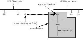
Remote Procedure Calls
Remote Procedure Call (developed by Sun Microsystems) provides the foundation supporting NFS among other network services, called RPC-based servers.
RPC defines a transparent distributed computing service by which a process is split into two components, the client and the server component. The client component is local to the host that is making the RPC call to the remote network shared resource. The server component manages the shared resource and processes and responds the RPC calls it receives from the client.
While the remote procedure is executing at the server's end, the local RPC-user process awaits the return results the way it would have waited if the call had been made to a local resource.
Transport Support Being a process/application layer protocol, RPC relies on transport layer protocols for the exchanging of requests and responses between RPC clients and servers. Under TCP/IP, RPC is supported over both transports UDP and TCP.
Most RPC activity is carried by the UDP transport protocol. This mostly the case because RPC routines live a relatively short life cycle, making the overhead associated with the creation and termination of TCP connections unjustifiably high. For this reason, message sequencing and reliability checks are built into most of the RPC servers. TCP connections are commonly established for the sake of transmitting large chunks of data.
In contrast to other TCP/IP applications, such as FTP and TELNET, RPC servers do not rely on well known transport port numbers. They are, instead, dynamically assigned an available port number at boot time.
A complete listing of the RPC servers supported on your host, look up the contents of the /etc/rpc file. Following is a partial listings of its contents:
rpcbind        100000    portmap sunrpc rpcbind
rstatd         100001    rstat rup perfmeter
rusersd        100002    rusers
nfs            100003    nfsprog
ypserv         100004    ypprog
mountd         100005    mount showmount
ypbind         100007
walld          100008    rwall shutdown
yppasswdd      100009    yppasswd
sprayd         100012    spray
llockmgr       100020
nlockmgr       100021
statmon        100023
status         100024
ypupdated      100028    ypupdate
rpcnfs         100116    na.rpcnfs
pcnfsd         150001
Each entry in this file includes (left to right) the server name, program number and optionally one or more aliases.
Program Number and Port Mapper Since RPC servers are dynamically assigned port numbers at startup time, there arises the requirement for a mechanism by which the servers can make themselves addressable by their clients. RPC achieves this by employing an arbitrator process, known as the port mapper, that listens for requests on behalf of RPC servers. Instead of addressing servers at port numbers, clients initially address them at well assigned program numbers (listed in the /etc/rpc file). At startup, every RPC server registers itself with the port mapper (implemented as rpcbind daemon).
Before a client requests an RPC service for the first time, it should contact rpcbind (that is, the port mapper) for the port number on which the desired RPC server is listening for requests. After a favorable response is obtained, the client caches the port number and uses it to contact the RPC server directly. Understandably, for clients to reach the port mapper, the latter must listen to port resolution requests on a well-known port number. The port number is 111.
Procedure Number Each RPC server is comprised of a number of procedures, where each procedure handles certain functionality of the service. NFS, for example, supports many procedures, of which we mention NFSPROC_READ, which a client uses to read from a file, NFSPROC_WRITE to write to a file, and NFSPROC_REMOVE to delete a file belonging to the NFS server. Every procedure is assigned a number which the client passes in an RPC request to identify the procedure it wants executed by the server.
Version Number Every implementation of the same RPC server is assigned a version number. A new implementation is always assigned a higher number. A new version of an RPC server is usually made to support earlier procedure implementations so that all versions are taken care of by a single server process.
It is not sufficient, therefore, that a client specifies, the RPC program number, the procedure number and the port number when passing an RPC request to the server. It must also specify the version number that the client supports. Unless the server and the client agree on a mutually acceptable version support level, the port mapper returns an error message complaining about version mismatch.
Hence, to uniquely identify a procedure to an RPC server, the client must specify the program number, the procedure number and the version number.
NFS Daemons
As are many UNIX services, NFS is implemented in a set of deamons. Some of the NFS-related deamons run on the server while others run on the client. Also a subset of the deamons run on both sides. Following is a description of what function each of the deamons provide as part of the overall NFS service:
| nfsd | is the NFS server daemon, it runs on the server and is responsible for handling, and responding, to client requests. nfsd handles client requests by decoding requests to determine the nature of the desired operation, and submitting the call to local I/O disk access mechanism for actual execution. nfsd is normally invoked when the system is brought up to run level three. For performance-related reasons, multiple instances of nfsd are invoked. |
| biod | is the block input/output daemon. It runs on NFS clients, and handles reading and writing data from and to the NFS server on behalf of the client process. Again, performance-related issues dictate that multiple instances of this daemon be invoked on the client. Be careful, however, because invoking too many instances of biod can potentially lead to degradation in performance. |
| mountd | runs on the NFS server. It is responsible for handling client mount requests. Looking back at Figure 20.30, when the command "mount -F nfs tenor:/efs /ifs" is issued on the command line on host jade, an NFS mount request is sent by the client to the NFS server. Unless host tenor is running mountd, it will not be able to honor the request and the mount is bound to fail. NFS servers run only one mountd. |
| lockd | run by both the client and server, this daemon handles file locks. On the client side the daemon issues such requests, whereas the server's lockd honors those requests and manages the locks. |
| Statd | run by both the client and server, this daemon maintains the status of currently enforced file locks. Its usefulness is particularly realized during server crashes as it helps clients to reclaim locks placed on files after the recovery of the server. |
Table 20.3 below shows lists the deamons that run on each side of the NFS service.
Table 20.3. Listing of deamons that are invoked by NFS on both the client and the server hosts. Notice how both lockd and statd deamons are invoked on both hosts.
| Client Daemons | Server Daemons |
| biod | nfsd |
| lockd | lockd |
| statd | statd |
| mountd |
Setting Up the NFS Server
Once you have decided which parts of the file system you want to share on the server with other hosts, you can proceed to setting up NFS.
Setting Up NFS on SVR4 Including Solaris 2.x Exporting a file system (that is, rendering it shareable) under SVR4 involves the use of the share command. The syntax of this command is:
share [-F nfs] [-o options] [ -d description] pathname
where,
| -F nfs | Specifies the type of exported filesystem. UNIX supports many different types of remotely accessible filesystems. Examples of such filesystems include RFS (Remote File Systems) and AFS (Andrews File System). This option can be omitted if NFS is the only distributed file system which your system supports. |
| -o options | specifies restrictions that apply to the exported filesystem. Table 20.4 lists the options and a brief description of their effects. |
| d description | A descriptive statement. |
| Pathname | Specifies the pathname to export (or share). |
Table 20.4. Options supported by the -o options upon mounting an NFS filesystem.
| Option | Description |
| rw=host[:host...] | allows read/write access to exported file system to the hosts specified in the host parameter. |
| ro=host[:host...] | Exports the pathname as read-only to listed hosts. If no hosts are specified, all clients, with exceptions stated using rw= option, are allowed read-only access. |
| anon=uid | Assigns a different uid for anonymous users (i.e. users with uid 0) when accessing pathname. By default anonymous users are assigned uid of user nobody. User nobody normally has same access privileges as public. |
| root=[host[:host...] | Allows root access privileges to user from the host host. The user's uid has to be 0. Unless specified no user is allowed root access privileges to pathname. |
| secure | Enforces enhanced authentication requirements before a user is granted access to an NFS mounted filesystem. |
In the scenario depicted in Figure 20.30, using the following share command allows host tenor to export and share the /efs subtree of the filesystem. Further, the exported file system is flagged rw, hence allowing other hosts read/write access to it:
# share -F nfs -o rw, ro=saturn -d "Just an example" /efs
The share command shown here allows no root access to the /efs directory.
The following share command, on the other hand, prevents all hosts but violin from accessing the filesystem:
# share -F nfs -o ro=violin /efs
Hosts, other than violin, attempting to mount the /efs directory, will fail and end up with the "Permission denied" message.
In the following example root privilege is granted to users from host jade:
# share -F nfs -o rw, root=jade /efs
To find out which filesystems are exported, simply enter share without command line arguments:
# share
-               /nfs   rw   ""
-               /efs   rw,ro=violin   ""
Automating Sharing at Boot Time Exporting (or sharing) file systems (under SVR4) at boot time is a simple matter that involves editing the /etc/dfs/dfstab file. In this file you should include as many share commands (using exactly same syntax explained above) to take care of all the directories you want exported by the NFS server. The following two share entries, for example, are extracted from the /etc/dsf/dfstab file on host tenor:
share -F nfs /nfs
share -F nfs rw, ro=satrun /efs
When the system enters run level three as it is brought up, /etc/dfs/dfstab contents will be read, and its share entries will be executed. No longer will the system administrator have to issue both share commands manually.
The program which is called from the /etc/init.d/nfs script to export all of the filesystems specified in the dfstab file is shareall. You may use it on the command line, as well, to force sharing, especially after you make changes to the /etc/dfs/dfstab which you want to implement immediately.
Setting Up NFS on BSD and Linux BSD-derived UNIX systems rely on the /etc/exports file to control which directories are exported. Entries in the /etc/exports file must follow the following syntax:
pathname [-option][,option]...
where, pathname specifies the directory being exported and option specifies access-pertinent privileges. Following is a description of the commonly supported options:
| rw[=hostname][:hostname]... | rw grants read/write privileges to hosts specified using the hostname parameter.
If no hostname is specified, then read/write access is granted to all hosts on the
network. rw is the default access privilege if no option is specified.
Here is an example: /usr/reports -rw=bass:soprano This entry grants read/write to the directory /usr/reports to users from hosts bass and soprano. Note that whenever hostnames are specified, the privilege applies to them only. Users from other hosts are granted read-only permission. In the above example, users on all hosts, but bass and soprano, have read-only access to /usr/reports directory. |
| ro | Specifies a read-only permission to the directory being exported. User attempts to write to the directory results in error messages such as "Permission denied", or "Read-only filesystem. |
| access=hostname[:hostname]... | Specifies the names of the hosts that are granted permission to mount the exported directory. If this option is not included in the entry affecting the exported directory, then all hosts on the network can mount that directory (i.e. the directory ends up being exported to every host). |
| root=hostname[:hostname]... | Grants root access privilege only to root users from specified hostname(s). Otherwise
(i.e. if no hostname is specified), root access is denied (by default) to
root users from all hosts. In this example, root access is granted to root users
from hosts violin and cello: /usr/resources root=violin:cello Since no ro or rw options are specified, the exported directory (/usr/resources) is by default read/writeable users from all hosts. |
For discussions on more options affecting NFS access privileges please refer to the man pages supplied by your vendor.
Every time the system is booted, the NFS startup scripts execute and process the contents of the /etc/exports file. Normally, for performance reasons, eight instances of the nfsd daemon are started and only one mountd (or rpc.mountd, as called by some systems) is started. The mountd daemon is responsible (as explained earlier) for mounting exported file systems specified in the /etc/exports file, in response to client mount requests.
Setting Up the NFS Client
On the client side, a user has to issue the mount command prior to attempting access to the exported path on the NFS server. For example, to access the exported /efs directory on NFS server tenor, the user must first issue the following mount command on a UNIX SVR4 operating system:
# mount -F nfs jade:/efs /rfs
As shown in Figure 20.30, /efs is the exported directory on host tenor, and /rfs is the mount directory. Once mounted, /efs or any directories below it can be accessed (subject to security restrictions) from host jade, using ordinary UNIX commands, and programs.
Following is the complete syntax of the mount command:
mount [-F nfs] [-o options] host:pathname mountpoint
where,
| -F nfs | specifies the type of the filesystem to mount. |
| - o options | specifies the mount options. Table 20.5 includes a listing of commonly used options. |
| host:pathname | Completely identifies the server and the resource directory being mounted. host is the hostname of the NFS server, and pathname is the pathname of the exported directory on this server. |
| mountpoint | Specifies the pathname of the directory on the client through which the NFS-mounted resource will be accessed. |
Table 20.5. Mount-specific options.
| Option | Description |
| rw | ro | Specifies whether to mount the NFS directory for read-only or read/write. The default is rw. |
| retry=n | Specifies the number of times mount should retry. This is normally set to a very high number. Check your vendor's documentation for the default value of n. |
| timeo=n | Specifies the timeout period for the mount attempt in units of tenths of a second. timeo is normally set to a very high number. Check you vendor's documentation for the default value. |
| soft | hard | Specifies whether a hard or soft mount should be attempted. If hard is specified the client relentlessly retries until it receives an acknowledgement from the NFS server specified in host. A soft mount, on the other hand, causes the client to give up attempting if it does not get the acknowledgment after retrying the number of times specified in retry=n option. Upon failure, a soft mount returns an error message to the attempting client. |
| bg | fg | Specifies whether the client is to reattempt mounting, should the NFS server fail to respond, in the foreground (fg) or in the background (bg). |
| intr | Specifies whether to allow keyboard interrupts to kill a process which is hung up waiting for a response from a hard-mounted filesystem. Unless interrupted, the process waits endlessly for a response, which in turn locks the session. |
mount command
Except for a few subtleties, the above description of the mount command applies to all variants of UNIX. You are advised, however, to check the man pages for the exact syntax that is peculiar to your variant.
Should a soft mounted filesystem fail to respond to a mount request, the request will be retried by the client for the number of times specified in the retry=n option. If the n retries are exhausted without any success getting an acknowledgement form the server, an error message is returned and the client stops retrying.
If the affected filesystem was mounted for read/write access, this mode of behavior may seriously impact the integrity of applications which were writing to this filesystem before the interruption in service occurred. For this reason it is recommended that read/write mountable filesystems be hard mounted. This guarantees that the client will indefinitely retry an operation until outstanding requests are honored, even in the event of a NFS server crash.
Unreasonably extended server failure may lead to locking up an application indefinitely while waiting for a response from a hard mounted filesystem. Hence, whenever a hard mount is desired it is important that keyboard interrupts are allowed (by specifying the intr option) to kill the process so that a user can recover the login session back to normal operation.
Following is a mount command which would be used to soft mount the /nfs/sales directory on the NFS server jade, with read-only access. The mount point is /usr/sales on host jade:
# mount -F nfs -o soft, ro tenor:/nfs/sales /usr/sales
To verify that a filesystem is indeed mounted, use mount without any command line arguments as follows:
# mount
/ on /dev/root read/write on Sat Feb 18 09:44:45 1995
/u on /dev/u read/write on Sat Feb 18 09:46:39 1995
/TEST on /dev/TEST read/write on Sat Feb 18 09:46:40 1995
/usr/sales on tenor:/nfs/sales read/write on Sat Feb 18 10:02:52 1995
The last line indicates the name of the mount directory, the name of the NFS server, and the name of the mounted filesystem.
Starting and Stopping NFS Services
Once all the necessary steps for automatic sharing and mounting of filesystems are completed, you can start NFS operation on both the server and the client hosts. While the deamons required to start NFS services are the same for all variants of UNIX, the startup procedure itself could be different.
Starting and Stopping NFS on SVR4 (not including Solaris 2.x) To manually start NFS using the command line, use the following command:
sh /etc/init.d/nfs start
This command automatically starts the same set of NFS daemons independent of whether the command was invoked on a client or a server. Depending on the vendor, anywhere from four to eight deamons of both nfsd and biod are started by the script. Starting multiple instances of these deamons has the impact of improving the overall performance of the NFS service.
The /etc/init.d/nfs script also starts all other daemons including lockd, statd, and mountd. All NFS daemons are invoked on both the server and clients because UNIX allows a host to assume both roles server and client. While the system is a server to clients on the network, itself can be a client to some other server(s).
Should the /etc/init.d/nfs script fail to run on your system, it could be because the system is not at run level 3. To check the state of your system, enter the following "who -r" command:
# who -r
   .       run-level 3  Nov 12 10:40    3    0    S
To bring the system up to run level three, if it is not there yet, enter the following init command:
# init 3
To bring up the system to run level three by default at boot time, you must ensure that the /etc/inittab file includes the following initdefault entry:
is:3:initdefault:
Upon checking the /etc/inittab file, you may find the following entry instead:
is:2:initdefault:
In this case, use your preferred editor to replace the 2 in the initdefault entry with 3. This guarantees that the system enters run level three when booted. A necessary condition for starting the NFS service on both the client and the server.
NOTE: As noted before, SVR4 allows for the auto-sharing (exporting at boot time) of directories specified in the /etc/dfs/dfstab. In like fashion, SVR4 allows for auto-mounting of remote file system resources based on entries in the /etc/vfstab file. Using the vfstab file, a system administrator can specify the name of the NFS server host, the mount directory, and some options affecting the way the remote resource is mounted. Consult your man pages for detail regarding the contents and syntax of entries to include.
Starting Up NFS on Solaris 2.x Solaris 2.x relies on two distinct scripts for the NFS server and client. The script that starts the NFS server (the deamons pertaining to exporting, mounting and responding to NFS service requests) is /etc/init.d/nfs.server.
The script responsible for starting the client deamons (such as biod, lockd, and statd) is /etc/init.d/nfs.server.
Breaking the scripts into two, on Solaris 2.x, optimizes on resource utilization as only the needed component (that is, server and/or client service) needs to be started.
Aside from splitting the scripts to two, one for the server and another for the client, the configuration and mechanisms of invoking NFS at system startup remain almost identical to the description provided under SVR4.
Starting Up NFS on Linux Similar to Solaris 2.x, Linux also relies on two distinct scripts for the startup of the NFS server and client components. The script that starts the NFS server is /etc/rc.d/init.d/nfs whereas the one that starts the client deamons is /etc/rc.d/init.d/nfsfs. Both scripts are fairly simple to read and understand.
Linux also allows for auto-mounting of NFS resources at boot time. For it to do so, however, the system administrator should have edited the /etc/fstab configuration file. The file is similar in function to SVR4's /etc/vfstab file, but not in entry contents and syntax. It consists of one entry per remote resource specifying the NFS server's name, the filesystem resource exported by that server, and options affecting the way the resource is to be mounted (including the mount point). For accurate depiction of this file, please refer to the man pages on your system.
Manual Unmounting and Unsharing of Filesystems Optionally, you can manually interrupt part of the service whether to troubleshoot, or reconfigure NFS on a host.
To selectively unmount a filesystem on a client, you simply have to enter the following umount command:
# umount mountpoint
where mountpoint is the name of the directory where the NFS filesystem is attached. Hence, to unmount, for example, the /efs directory of server tenor from the /rfs directory on client jade (see Figure 20.30), enter
# umount /rfs
To unmount all filesystems you can either enter umount as many times it takes to get the job done, or simply use the umountall command:
# umountall
Be careful, however, with umountall, because it also unmounts local file systems.
Domain Name Service Implementation
The subsection "Naming Services" provided a conceptual level treatment of name services as defined by DNS. In this section you will be shown how to setup the DNS service for a hypothetical environment. The discussion aims at highlighing the most common aspects of setting up the service. Dealing with the all the common aspects and scenarios of setting up DNS cannot be fulfilled in one chapter; for this reason, and to facilitate the learning of the underlying procedures only one simple scenario is dealt with.
The scenario is based on a fictitious domain, harmonics.com pertaining to a hypothetical institute of music Harmonics, Inc. Figure 20.31 shows the network layout of this company. As shown, the network is made of two networks, a Class A network (100.0.0.0), and a Class C network (198.53.237.0). Multihomed host jade connects both networks. Also, the network is connected to the Internet via a router called xrouter with IP address 100.0.0.10. The diagram shows the IP addresses assigned to all hosts on the network.
Figure 20.31.
The harmonics.com network layout.
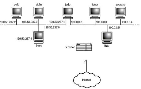
Being a commercial organization, Harmonics, Inc. was registered under the com domain as harmonics.com as reflected in Figure 20.32. Since harmonics.com is assigned two network addresses, it is also delegated the administration of both reverse domains the 100.in-addr.arpa and 237.53.198.in-addr.arpa. Whereas harmonics.com maintains host information, such as host-to-IP address associations, the reverse domains are used to maintain the inverse mappings (that is, the IP-to-host name associations).
Figure 20.32.
The domains delegated to Harmonics Inc.'s administration authority.
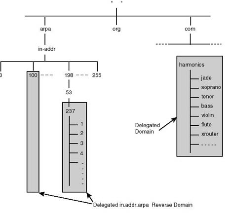
Since host jade is connected to both networks, it would be a good idea to bring up DNS name service on it. This way all hosts will have a DNS server directly attached to their network, resulting in better response time. Furthermore, host jade will be configured as the primary DNS server. In addition on each of the networks a secondary DNS server will be brought up. This way should host jade go down, both networks will have backup DNS server to fall on for securing continued DNS service. Because harmonics.com is the domain name, every host is assigned domain name in compliance with the following syntax:
hostname.harmonics.com
Hence, jade's and cello's domain names become jade.harmonics.com and cello.harmonics.com. Hereafter, the "host name" and the "domain host name" will be used interchangeably.
Besides setting up DNS servers, configuring name services involves setting up all the DNS clients on the network. Next section proceeds how to setup the DNS client. After that setting up the servers is discussed in a fair amount of detail.
Configuring the DNS Client
The DNS client, known as the resolver, is built into each of the TCP/IP applications and is responsible for resolving DNS queries on behalf of the invoked application. DNS queries can be various types. Most common of them all is the hostname-to-IP address resolution query, known as A type query. Reverse queries (that is, IP address-to-hostname resolution queries) are known as PTR or pointer queries.
Unless configured to contact a name server, the resolver normally checks the /etc/hosts file to get the IP address corresponding the name of the host the application specifies.
All you have to do to configure the resolver on a host, is to create a simple file known as /etc/resolv.conf. Using this file, the system administrator defines the domain name to which the host belongs (in our scenario, this is the harmonics.com domain), the IP addresses of up to three name servers (independent of whether the servers are primary, secondary, or even cache servers). Following are the contents of a sample /etc/resolv.conf file:
# keyword    value

domainname    harmonics.com
nameserver    100.0.0.2
nameserver    198.53.237.3
As shown, the file is made of simple entries, each of which is made of two parts, a keyword and a value. The first entry includes the keyword domainname followed by the domain name to which the host is said to belong. Accordingly, by virtue of this entry (that is the domainname) the host now knows where in the domain name space it belongs. The last two entries specify the name servers (by virtue of keyword the keyword nameserver) that the resolver ought to forward name queries to for resolution. According to these entries, and Figure 20.32, the IP addresses correspond to hosts jade and cello. Notice that the entries make no indication as to the nature of the server (that is, as being primary, secondary, or otherwise).
Should a user on a DNS-configured client enter the following command, for example:
$ ftp tenor.harmonics.com
The resolver would then issue an A type query to a name server on the network that is specified in the /etc/resolv.conf file. Of the two shown above in the listing of the sample /etc/resolv.conf, the server 100.0.0.2 (that is, host jade) is sought first for resolution, simply because it happens that the first nameserver record pertains to jade not cello. Should host jade fail to respond, cello is then contacted next by the client. Ultimately, a successful query returns the IP address of host tenor to the resolver which in turn hands it off to ftp.
From what has just been said, it makes sense to specify name servers in the /etc/resolv.conf file in ascending order of geographic proximity (that is, the closest at the top, followed by the next closest, and so on).
DNS Database and Startup Files
Configuring a name server involves the creation of many database and startup files. The number of files, as will be seen later, varies with the size of the organization, its internetwork structure, and the number of domains it has been delegated to administer. In the following discussion four different file types will be presented. Depending on the type of the name server (primary, secondary, or cache) you may end up configuring different combinations of these file types. You may also end up configuring multiple files of the same type.
The following are the generic names, and basic definition (leaving the in-depth details for later on) corresponding to each of the DNS database and startup files:
| named.hosts | this file defines the domain for which the name server is authoritative, and mainly contains hostname to IP address mappings. Remember, an authoritative server is the one originating the data pertaining to the domain its being authoritative for. In other words, its where the domain data is created and updated and from which data is disseminated to other servers on the network or the Internet. |
| named.rev | this file defines the reverse in-addr.arpa domain for which the name authoritative. It also contains the IP address to hostname reverse mapping records. |
| named.local | this file is minimal in contents. It contains information just enough to resolve the 127.0.0.1 loopback address to localhost. |
| named.ca | this file contains the names and addresses of the Internet's root domain servers. Using the information maintained in this file, a name server will be able to contact root servers for name queries as explained earlier in the chapter. |
| named.boot | the first file which is looked up by named (the DNS daemon) at start up. Using its contents, named determines the database filenames, and their location, in the file system on this host, as well as remote hosts. |
You don't have to stick to these filenames. As will be shown later, you can give them names that make better sense to you and make them recognizable by named (the DNS deamon) by the proper utilization of the named.boot file.
Domain data is maintained in these files in the form of resource records (RR's). Resource records must follow a structure as defined in RFC 1033 for DNS to behave flawlessly . In the following few subsections, a group of resource records will be presented. We will concentrate on the ones immediately required to set up a minimal name service (only for the purpose of the bidirectional mapping of host names and IP addresses).
DNS Resource Records (RR)
DNS RFC 1033 defines a multitude of resource record (RR) types. Each type is responsible for tackling an aspect of the global database. A type records for example, are used to maintain hostname-to-IP address associations, whereas NS (name server) records are used to maintain domain name-to-name server associations.
Following is a description of the resource records that are required to implement the objectives stated in the last section only. Readers interested in more information are referred to the noted RFC.
The general syntax of any RR is as follows:
[name] [ttl] class type data
where,
| name | Is the name of the resource object being described by this resource record. name can be as specific as the name of a host or as general as the name of a domain. If it's left blank, the name of previous record is assumed. Two widely used special values for name are: 1) the single dot "." which refers to the root domain, and 2) the @ sign which refers to the current origin, derived from the current domain name (more on this later). |
| Ttl | Is the Time-to-live value, in seconds. For better performance, a DNS client normally caches the information it receives from the name server. ttl defines the duration for which this entry can be trusted, and therefore kept in cache. If not included, then the default specified in the SOA applies. |
| Class | Defines the class of the DNS record. DNS recognizes several classes of RR of which IN (i.e. Internet) is the only class relevant to this discussion. Some of the other classes are HS (Hessiod name server), and CH (Chaosnet information server). |
| Type | Defines the type of information the RR record represents. The most commonly used record types are SOA, NS, A, MX and PTR. An A RR record, for example contains the hostname-to-IP address mapping and belongs to the named.hosts file, while the PTR RR record does exactly the opposite (i.e. it reverse maps the address to the corresponding hostname), and belongs to the named.rev file. More on record types later in the section. |
| Data | The actual data pertinent to the object specified in name field. The nature of the contents of data varies with the RR record. data represents an IP address if RR is of type A, as opposed to hostname if RR was of type PTR. |
In the following subsections, a few RR types are described. Information about other types is available in RFC 1033. The order in which the various RR types is presented should not suggest the order in which they have to be placed in the database files. RR records can in fact be maintained in whichever order you desire as long as the syntax governing each type is well adhered to.
Start of Authority (SOA) Resource Record The SOA record identifies the upper boundary of a partition (also known as a zone) of the global DNS database. Every configuration file must contain an SOA record identifying the beginning of the partition for which the server is authoritative. All RR records following the SOA record are part of the named zone. Looking at Figure 20.32, a primary name server for the harmonics.com domain recognizes the partition boundaries by including an SOA record in its named.hosts configuration file.
The syntax of the SOA record is:
[zone] [ttl] IN SOA origin contact (serial refresh retry expire minimum)
where, zone identifies the name of the zone. ttl was described above and is left blank in SOA records. IN identifies the class, SOA is the record type and the remaining part is the data affecting the named zone.
As shown in the syntax, the data field itself is structured where
| origin | Refers to the primary name server for this domain. In harmonics.com's case this is jade.harmonics.com. |
| contact | Refers to the e-mail address of the person responsible for maintaining this domain. The root's e-mail address is commonly used. You can specify the e-mail address of any account you want. Assuming that login root on jade.harmonics.com. is responsible for the harmonics.com. domain, contact would then be specified as root.jade.harmonics.com. Notice how the notation to specify the e-mail address uses the dot "." instead of the @ character after root. |
| Serial | Refers to the version number of this zone file. It is meant for interpretation and use by the secondary server, which transfers data from the primary server. Normally, the very first version number is 1. The serial number must be incremented every time the file containing this resource record is modified. A secondary name server relies on this field to determine whether its database is in synchronization with the master replica maintained by the primary server. Before initiating any transfer, the secondary server compares its own version number with that of the primary's file. A larger primary version number flags an update. Failure to increment serial as changes are made to the file prevents the secondary server from transferring and including, the updates in its tables. This may cause serious disruption in the way the DNS service behaves itself on the network. |
| refresh | Refers to how often, in seconds, a secondary server should poll the primary for changes. Only when a change in version number is detected is the database transferred. |
| Retry | Refers to how long, in seconds, the secondary server should wait before re-attempting zonal transfer if the primary server fails to respond to a zone refresh request. |
| Expire | Defines the duration of time, in seconds, for which the secondary server can retain zonal data without requesting a zone refresh from the primary. The secondary server ought to discard all data upon expire, even if the primary fails to respond to zone refresh requests. |
| Minimum | Defines the default time-to-live (ttl) which applies to resource records whose ttl is not explicitly defined (see description of the syntax of RR record). |
As an example, the SOA record defining the upper boundary of the harmonics.com domain should read as follows:
harmonics.com.    IN    SOA    jade.harmonics.com. root.jade.harmonics.com. (
                2    ; Serial
                14400    ; Refresh (4 hours)
                3600    ; Retry (1hr)
                604800      ; Expire ( 4 weeks )
                86400 )    ; minimum TTL (time-to-live)
This record must be included in the named.hosts file. It makes the DNS server aware of where its authority (and responsibility) starts. Accordingly, named.hosts must contain all the necessary data for answering name queries pertaining to hosts belonging to harmonics.com. The data can be in the form of resource records which explicitly includes host name to IP address mappings, or pointers to other DNS servers for which authority over subdomains (if any) is delegated.
Address (A) Resource Record A address resource records belong to the named.hosts file. An A record maintains the host name-to-IP address association. Whenever a name server is queried for the IP address of host, given its name, the server fetches for A records for one with a matching object name and responds with the IP address described in that record.
Following is the syntax of the A record:
[hostname] [ttl] IN A address
Where,
| hostname | Is the name of the host being affected. The host name can be specified relative to the current domain, or using a fully qualified domain name (i.e. relative to the root domain). For example, host cello can be entered just as such (that is, cello) in which case the name is said to be relative to the current domain, or it can be entered as cello.harmonics.com. in which case the name is fully qualified. The dot trailing the fully qualified name is significant and must be included. |
| ttl | Is the minimum time-to-live. This is normally left blank implying the default as defined in the SOA record. |
| IN | Defines the class, which is almost always Internet class. |
| A | Defines the record type (an address record) |
| address | The IP address corresponding to the hostname. |
As an example, the following is the A record pertaining to jade.harmonics.com.
jade.harmonics.com. IN A 100.0.0.2
The host name is a fully qualified domain name (FQDN). For this reason, it is mandatory that it ends with a dot ".". Alternatively, it can be written as:
jade IN A 100.0.0.2
Since jade belongs to harmonics.com., DNS has enough intelligence to qualify the name by appending the domain name to jade, becoming jade.harmonics.com.. More details on the period (or dot) rule will be provided later.
Name Server (NS) Resource Record Name server resource records are the glue that makes the DNS hierarchical structure stick. An NS record defines which name server is authoritative for which zone or subdomain. It is especially used to point a parent domain server, to the servers for their subdomains.
As shown in Figure 20.33, a name server authoritative for the com domain must include an NS record identifying the server which is authoritative for the harmonics.com domain (i.e. jade.harmonics.com.).
Figure 20.33.
A server authoritative for the .com domain must include an NS record identifying
the server that is authoritative for the harmonics.com domain (jade.harmonics.com).
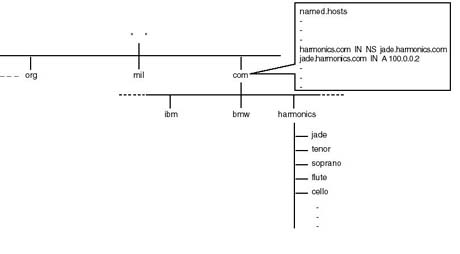
The syntax of the NS record follows:
[domain] [ttl] IN NS server
Where
| domain | Is the name of the domain for which server is an authoritative name server. |
| Ttl | Time-to-live. If left blank, the default specified in the SOA record applies. |
| IN | Again, the class is IN (internet) |
| NS | Identifies the RR record type as NS (i.e. a pointer to a name server). |
| server | The name of the host providing authoritative name service for the domain specified in domain. |
Applying this to the harmonics.com. situation, a server for the com domain should contain the following NS record in its named.hosts file:
harmonics.com. IN NS jade.harmonics.com.
This NS record must also be included in the named.hosts file of jade.harmonics.com. When a server for the com domain is queried for a the host IP address of cello.harmonics.com. it checks its database to determine that jade.harmonics.com. is the server to which the query should be redirected. Hence, the com server returns the IP address of the jade, not its name, to the client station issuing the query. This means that it is not enough to include an NS record describing which server is authoritative for a given domain. The NS record should always be coupled with an A record specifying the address of the domain's server. Hence, the com server in question must include both of the following records in order to redirect queries pertaining to the harmonics.com. domain to jade:
harmonics.com. IN NS jade.harmonics.com.
jade IN A 100.0.0.2
Canonical Name (CNAME) Record A CNAME record defines an alias pointing to the host's official name. It normally belongs to the named.hosts file. The following is the syntax of the CNAME record:
aliasname [ttl] IN CNAME [host]
where
| aliasname | Defines the alias for the host specified in host. |
| ttl | Defines the time-to-live. If left blank the default specified in SOA record applies. |
| IN | Is the IN class |
| CNAME | Identifies the record as CNAME type. |
| host | Is the official name of the host. |
The following is an example of a CNAME record:
fake.harmonics.com. IN CNAME cello.harmonics.com.
If a client issues a name query for host fake, the name server replaces fake with cello, using the above CNAME record, during its search for the queried information.
CNAME records are particularly useful whenever host name changes need to be made. What you would do in such a situation is change the official name, then maintain the old one as an alias for the new official name. Allow a grace period until users are accustomed to the new name, and applications affected by name changes are reconfigured.
Pointer (PTR) Records PTR records are used to map IP addresses to names. To reverse resolve IP addresses into host names, the Internet included the in-addr.arpa top level domain in its DNS tree. Below that domain, a subtree is created such that each network ID had a domain named after itself. For example, network id 198.53.237.0 has 237.53.198.in-addr.arpa. for a reverse domain (Refer to the section "Name Service" earlier in the chapter for an understanding of the reverse naming convention). Normally, when an organization like Harmonics (the fictitious company) is delegated authority over its domain harmonics.com, NIC delegates the organization the authority over the reverse domain corresponding to the network IDs belonging to that organization. In Harmonics' case the reverse domains are 100.in-addr.arpa, and 100.in-addr.arpa.
PTR records are maintained in the named.rev file, and are used to reverse-map the IP address to a host name.
Following is the syntax of the PTR record:
name [ttl] IN PTR host
where
| name | Specifies the reverse domain name of the host. The reverse domain name of a host
has the following format: reverse_IP_address.in-addr.arpa |
| Since cello's IP address is 198.53.237.2, its reverse_IP_address becomes 2.237.53.198. Hence, the reverse domain name of the host cello becomes 2.237.53.198.in-addr.arpa. | |
| [ttl] | Specifies time-to-live. If left blank, the default specified in the SOA record is assumed. |
| IN | Record is class IN. |
| PTR | Signifies the record as being of type PTR. |
| host | Specifies the host name. |
Referring to host cello, for example, a PTR record resolving its IP address to host name should read as follows:
2.237.53.198.in-addr.arpa IN PTR cello
Mail Exchanger (MX) records A mail exchanger (MX) record identifies where to deliver mail for a given domain. When a user originates a mail message, the host issues an MX query to the name server specified in the /etc/resolv.conf file. The MX query includes the domain name specified by the user as part of the e-mail address of the recipient. If, for example, the specified recipient is jsmith@harmonics.com, then the MX query includes the domain name harmonics.com implying the question "where should e-mail pertaining to users in the harmonics.com domain be delivered to?". The queried name server fetches its MX records, finds an entry matching the specified domain, and responds with the IP address of the host handling deliveries on part of that domain.
MX records belong to the named.hosts file. Following is the syntax of MX records:
domainname IN MX preference mx_host
where
| domainname | Specifies the domain for which the host specified in mx_host is acting as the mail exchanger |
| IN | Specifies the class as IN |
| MX | Specifies the type as MX |
| preference | Specifies the preference level of the designated server. preference can assume values between 0 and 65535). |
| A domain may have more than one host acting in the capacity of mail exchanger on
its behalf, each assigned a different preference value. The preference value has
a relative significance only. Mail delivery is first attempted to mail exchangers
with lower preference value. Should the attempt fail, delivery is next attempted
to the mail exchanger that is next in preference. Here is an example to help explain
the concept: harmonics.com IN MX 1 flute.harmonics.com. harmonics.com IN MX 2 bass.harmonics.com. |
|
| According to the two MX records, both hosts flute and bass are mail exchangers for the harmonics.com. domain, with preferences 1 and 2 respectively. Accordingly, mail delivery, addressed to auser@harmonics.com, should be attempted to flute first for being of higher preference, should flute fail to respond, delivery should be attempted to bass next. | |
| mx_host | Identifies the server where mail to domainname should be delivered |
The following sections will help you put what has just been explained about resource records in perspective. You will be shown how to setup both a primary and secondary servers as well as cache servers.
Configuring a Primary Name Server
The following few subsections describe the contents of the database files required to bring up named (that is, the DNS deamon as a primary name server on host jade. As will be shown later, the success of implementing DNS services is almost entirely reliant on how well configured and behaved is the primary server. Setting up primary servers is more tedious and time consuming than any of the other server types. Setting up a primary name server involves creating and updating the following files:
- named.hosts
- named.rev
- named.local
- named.ca
- named.boot
named.hosts named.hosts primarily maintains the hostname to IP address mappings for all hosts in the designated zone. In harmonics.com's case, since the domain is not partitioned, named.hosts must contain the name to IP address mappings for all hosts on this network. In addition to these mappings, named.hosts may contain other information such as names of hosts acting as mail exchangers (i.e. mail routers), or CPU type, and well known services supported by a host. For the purpose of simplicity, a minimal service including name-to-address, and address-to-name mappings, will be described. The description will be based on the DNS setup files maintained on hosts jade and cello (jade being the primary and cello being the secondary) in support of name services for the harmonics.com domain.
Given what has been learned so far, and that jade is the primary server for the harmonics.com domain, this is what jade's named.hosts file should look like:
;
; Section 1: The SOA record
;
harmonics.com.    IN    SOA    jade.harmonics.com. root.jade.harmonics.com. (
                2    ; Serial
                14400    ; Refresh (4 hours)
                3600    ; Retry (1hr)
                604800      ; Expire ( 4 weeks )
                86400 )    ; minimum TTL (time-to-live)

;
; Section 2: The following are the name server for the harmonics domain. Notice how the second
; entry does not specify the domain name for which cello is being the name server. This implies that
; domain name is same as one specified in previous record.
;
harmonics.com.    IN    NS    jade.harmonics.com.
        IN    NS    cello.harmonics.com.
;
; Section 3: The following are the mail exchangers of the domain harmonics.com
;
harmonics.com.    IN    MX    1  flute.harmonics.com.
        IN    MX    2  bass.harmonics.com.
;
; Section 4: The following records map hosts' canonical names to their corresponding
; IP addresses
;
localhost.harmonics.com.     IN A    127.0.0.1
;
tenor.harmonics.com.    IN A    100.0.0.3
soprano.harmonics.com.    IN A    100.0.0.4
flute.harmonics.com.    IN A    100.0.0.5
xrouter            IN A    100.0.0.10
cello.harmonics.com.    IN A    198.53.237.2
violin.harmonics.com.    IN A    198.53.237.3
bass.harmonics.com.    IN A    198.53.237.4
;
; Section 5: Multihomed hosts
;
jade.harmonics.com.    IN A    198.53.237.1
            IN A    100.0.0.2
The file is conveniently broken down into sections, with each being titled by the section number and purpose of that section.
Section 1 contains the SOA record, which declares jade.harmonics.com as being the DNS authoritative server for the harmonics.com domain. A named.hosts file can contain only one SOA record, and it must be the first record in the file. The record also indicates that correspondence regarding this domain should be addressed to root@jade.harmonics.com (remember that the dot "." following root should be replaced with the familiar @ character). Refer to the description of SOA records for details on the values enclosed in parenthesis.
Section 2 includes two NS records declaring hosts jade and cello as name servers for the harmonics.com domain. Notice that the records do not specify which of the two servers is the primary as opposed to being the secondary server. The type of the name server is defined, as you will see later, in the named.boot file.
Section 3 includes two MX records identifying hosts flute and bass as the mail exchangers for the harmonics.com domain. Host flute is set at a higher priority than bass.
Section 4 includes all of the A (address) records which map host names to IP addresses. When a client station queries a name server for the IP address of a given host, named scans the A records in its named.hosts for one matching the requirement, and returns the corresponding IP address to the querying station.
Reflecting on section 5, notice how, corresponding to jade, being a multihomed host, there are two A records. Whenever, named is queried for the IP address of jade, or any multihomed host, named simply returns all the addresses if finds in its A records. To achieve optimal performance named returns the address closest to the querying station first, followed by the other ones in order of proximity.
named.rev Using the named.rev file, named attempts to resolve PTR type queries--i.e. given the host name, named responds the query with the IP address associated with that host in the named.rev file. In Addition to PTR records, named.rev must also include an SOA record marking the boundaries of the reverse domain for which the server is authoritative.
Corresponding to a network assigned more than one network ID, multiple named.rev-type files must be created, one per in-addr.arpa domain under different names. You will be shown later how to configure the boot process (via named.boot file) of named to recognize such files. Following are the conventions used in this chapter for naming the named.rev-type files.
reversenetID.rev
where reversenetID is the assigned network id.
Since Harmonics, Inc. is assigned two network IDs (these are 100.0.0.0 and 198.53.237.0), the named.rev-type files become 100.rev and 237.53.198.rev.Each of these files contains an SOA record defining its start-of-authority, and the PTR records pertaining to the reverse domain. Following are the complete listings of each of the reverse domain files as created on host jade:
100.in-addr.arpa.    IN SOA    jade.harmonics.com. root.jade.harmonics.com (
                1     ;serial
                14400    ; Refresh (4 hours)
                3600    ; retry   ( 1 hour )
                604800    ; expire  ( 1 week )
                86400 ) ; TTL = 1 day
;
; name servers
;
100.in-addr.arpa.    IN NS    jade.harmonics.com.
100.in-addr.arpa.    IN NS    cello.harmonics.com.
;
; Reverse address mappings
;
2.0.0.100.in-addr.arpa.    IN    PTR    jade.harmonics.com.
3.0.0.100.in-addr.arpa.    IN    PTR    tenor.harmonics.com.
4.0.0.100.in-addr.arpa        IN    PTR    soprano.harmonics.com.
5.0.0.100.in-addr.arpa        IN    PTR    flute.harmonics.com.
10.0.0.100.in-addr.arpa    IN    PTR    xrouter.harmonics.com.
Following is a listing of the contents of 237.53.198.rev file:
237.53.198.in-addr.arpa. IN SOA  jade.harmonics.com. root.jade.harmonics.com. (
                    1    ; serial
                    14400    ; refresh ( 4 hr )
                    3600    ; retry ( 1 hr )
                    604800    ; expire ( 1 week )
                    86400 )    ; TTL = 1day
;
;
; name servers
;
237.53.198.in-addr.arpa.  IN     NS    jade.harmonics.com.
237.53.198.in-addr.arpa.  IN    NS    cello.harmonics.com.
;
;
; Reverse address mappings
;
1.237.53.198.in-addr.arpa. IN    PTR    jade.harmonics.com.
2.237.53.198.in-addr.arpa. IN    PTR    cello.harmonics.com.
3.237.53.198.in-addr.arpa. IN    PTR    violin.harmonics.com.
4.237.53.198.in-addr.arpa. IN    PTR    bass.harmonics.com.
Notice how closely the organization of the first two parts of each file follows that of named.hosts. All files start with an appropriate SOA record marking the upper boundaries of the in-addr.arpa domain for which the server is authoritative. Next is a block of NS records, declaring the name servers which have authority for the domain. In all three files, both jade and cello are declared as domain name servers.
The last part consists of PTR records. Each of these records contain the IP address to domain name associations which named uses for reverse address resolution.
An interesting observation to highlight is that even if cello is on the Class C network, this did not stop it from being a server for the Class A 100.in-addr.arpa reverse domain. The point being made here is that the DNS service is a logical service independent from the physical topology. Similarly, on the Class A network, we could install a server that is authoritative the reverse domain 237.53.198.in-addr.arpa without impacting the availability of the service.
named.local If you re-examine the named.hosts file, you will find that it contains an entry corresponding to the special loopback host name localhost. This entry maps localhost to the familiar IP address 127.0.0.1. Yet there is no PTR record in any of the reverse domain data files (listed above) which takes care of the reverse mapping. None of those files is suitable for such a PTR record as the loopback address belongs to none of the in-addr.arpa domains that the files support.
To remedy the discrepancy, a new reverse domain file is required. This file is called, by default, named.local. Following are the file contents:
0.0.127.in-addr.arpa. IN SOA jade.harmonics.com. root.jade.harmonics.com. (
                1    ; serial
                14400    ; refresh ( 4 hours )
                3600    ; retry ( 1 hour )
                604800    ; expire ( 1 week )
                86400 )    ; TTL = 1 day
;
; name servers
;
0.0.127.in-addr.arpa.    IN    NS     jade.harmonics.com.
0.0.127.in-addr.arpa.    IN    NS     cello.harmonics.com.
;
; reverse address PTR mapping
;
1.0.0.127.in-addr.arpa. IN    PTR     localhost
Compare this file with any of the reverse domain files listed in the previous section. You will find that its organization is identical to those files. As can be understood from the SOA record this file identifies jade.harmonics.com as the server originating the 0.0.127.in-addr.arpa domain. Again, there are two NS records identifying both jade and cello as the name servers for this domain. Finally, there is only one PTR record to take care of the reverse address resolution of the loopback address (127.0.0.1) to the loopback host name localhost.
named.ca As explained earlier in the chapter, rather than forcing a server to undergo the entire resolution referral process in order to respond to identical name queries, DNS allows the server to respond from data its cache. The cache is designed to improve the overall performance of DNS. This is achieved by saving in memory responses to queries that clients submit to servers. Furthermore, servers also cache all data they discover during the referral process that led to the desired response. This helps DNS servers to acquire, overtime, considerable "knowledge" about the global DNS structure and keeping this knowledge locally accessible. This approach improves on both response time and network traffic.
To further improve the performance of the name service, DNS defines an additional cache-related file called named.ca. Using this file, data pertaining to other domains, neighboring or remote, can be maintained, including name servers authoritative for those domains as well as A records identifying their IP addresses. All data contained in the named.ca file is used to initialize the cache buffers in the DNS server every time the named deamon is started--a process that cuts down on the referral processes and the associated learning process that the server has to undergo to discover the DNS service structure.
For reliability, you should include only information you believe to be stable for prolonged periods. You also ought to periodically verify the validity and accuracy of the included data.
One of the most commonly included pieces of information in the named.ca file is information about the Internet root servers. This information is stable over long periods of time. It makes sense to initialize your server's cache with this information, given the likelihood that users on your networks will want to reach places on the Internet. A minimal named.ca file should, therefore, look as shown below:
;
; Section 1: NS records for the root domain servers
;
.    99999999    IN    NS    A.ROOT-SERVERS.NET
99999999    IN    NS    B.ROOT-SERVERS.NET
99999999    IN    NS    C.ROOT-SERVERS.NET
99999999    IN    NS    D.ROOT-SERVERS.NET
99999999    IN    NS    E.ROOT-SERVERS.NET
99999999    IN    NS    F.ROOT-SERVERS.NET
99999999    IN    NS    G.ROOT-SERVERS.NET
99999999    IN    NS    H.ROOT-SERVERS.NET
99999999    IN    NS    I.ROOT-SERVERS.NET
;
; Section 2: Root servers A records
;
A.ROOT-SERVERS.NET    99999999    IN    A   198.41.0.4
B.ROOT-SERVERS.NET     99999999    IN    A   128.9.0.107
C.ROOT-SERVERS.NET    99999999    IN    A   192.33.4.12
D.ROOT-SERVERS.NET    99999999    IN    A   128.8.10.90
E.ROOT-SERVERS.NET    99999999    IN    A   192.203.230.10
F.ROOT-SERVERS.NET    99999999    IN    A   192.5.5.241
G.ROOT-SERVERS.NET     99999999    IN    A   192.112.36.4
H.ROOT-SERVERS.NET    99999999    IN    A   128.63.2.53
I.ROOT-SERVERS.NET    99999999    IN    A   192.36.148.17
As can be seen, this named.ca file is made of two blocks of entries. The first one contains NS records identifying the names of the root servers. There are two thing that you should have noticed in this file; the dot "." in the first column at the beginning of the first NS record, and the lack of object names in the subsequent NS records (refer to the general syntax of RR records for details). Since the root domain is represented by a null character, the dot "." is the character used in DNS files. Also, whenever multiple contiguous records refer to the same object, the name field can be left blank in subsequent records following the first one. Hence, since all the NS records pertain to root servers, only the first record had to include the name of the object being affected (the root domain).
The second section of named.ca contains A records pertaining to the servers defined in the first section.. Whenever named is brought up, it reads named.ca and caches all of the information contained in this file, hence providing immediate access to root servers.
TIP: A current list of root name servers is always available through anonymous ftp from nic.ddn.mil.in the /netinfo/root-servers.txt file.
NOTE: It is your responsibility to regularly verify the validity and accuracy of the information contained in named.ca, including information about root servers. Failure to do so, may seriously disrupt name service on your network, leading to undesirable degradation in performance. NIC is responsible for the information on an as-is basis at the time of downloading the root-server.txt file cited above.
named.boot: the Startup File At boot time, the DNS server references the named.boot file for information regarding its authority and type (whether primary, secondary, or cache server). Following code shows how DNS is started on a SVR4:
#
if [ -f /etc/inet/named.boot -a -x /usr/sbin/in.named ]
then
    /usr/sbin/in.named
fi
Starting named Deamon
Although the code shown above is extracted from TCP/IP startup script /etc/inet/rc.int pertaining to SVR4 UNIX operating system, other UNIX platforms implement same code for doing the same job.
As shown, before the DNS deamon (in.named) is invoked, the code checks for the existence of the startup file named.boot file. As implied by the code the boot file could have been given any name (not necessarily named.boot) as long as the code is modified to reflect that name. Using named.boot, the DNS determines where the database files are including named.hosts, named.rev, named.ca and named.local. It also uses the file to determine the extent of it authority and type, as mentioned before.
The following is the listing of the file named.boot as it should be on jade to bring it up as a primary name server:
directory    /etc/named

primary    harmonics.com    named.hosts
primary    100.in-addr.arpa        100.rev
primary    237.53.198.in-addr.arpa    198.53.237.rev
primary    0.0.127.in-addr.arpa    127.localhost
cache    .                named.ca
Each of the lines is a record delivering a piece of information that helps the DNS deamon to configure itself. Each line, or record, has to start with a keyword bearing some significance to the configuration process. Here is a description of what does each record do:
- Using the keyword directory, the first record tells DNS deamon
that the default location where all the database files can be found is the /etc/named
directory in the server's file system.
- The second, third, fourth, and fifth records start with the keyword primary,
each followed by a domain name. This explicitly tells the server that it is authoritative
for each of the specified domains and that it is acting in the capacity of a primary
server. The last field of each record specifies the file that contains the records
pertinent to the specified domain. For example, upon reading the second record, named
self-initializes as being the primary server for the harmonics.com domain
and initializes its memory to the contents of the /etc/named/named.hosts
file.
- The last record specifies that the server is acting as a cache server for the root domain. Moreover, it specifies named.ca as the file (in /etc/named directory) that contains the cache initialization data.
Database FilenamesAs mentioned earlier in the chapter, database filenames can be anything you want. Reflecting on the contents of named.boot file, notice how the server can tell which files constitute the database by interpreting the last field of each record. Consequently, should you decide to use a different name for the named.hosts file, for example, all you need to do is to replace named.hosts with the filename you desire in the named.boot startup file.
The above concludes the steps required to configuring and starting a DNS primary server. Now let's have a look at how to setup a secondary server.
Configuring a Secondary Name Server
By definition, a secondary name server is a server that derives data pertaining to the zone it supports from a primary authoritative server. A secondary server does not have its own named.hosts-type and named.rev-type files. Rather, whenever started, a secondary server undergoes a zonal transfer process during which it requests the primary server to transfer copies of both files. Consequently, the secondary server initializes its memory with the contents of the transferred files for use in responding to name queries.
Since you won't be required to create and update the named.hosts and named.rev-type files, configuring a secondary server becomes a trivial matter that involves configuring three files, named.boot, named.ca and named.local. To simplify your life, copy all three files from the primary server over to the machine where you intend to bring up the secondary server. In our scenario, since host cello is required to act as a secondary server, then the three files, just mentioned, should be copied over to its file system from host jade's file system.
The only file which requires a few changes after being copied to the host serving as a secondary DNS server is named.boot. The following is how named.boot on cello should read:
directory    /usr/lib/named

secondary    harmonics.com    100.0.0.2
secondary 100.in-addr.arpa    100.0.0.2
secondary 237.53.198.in-addr.arpa    100.0.0.2
primary    0.0.127.in-addr.arpa    named.local
cache    .                named.ca
As can be seen from this, the configuration of named.boot includes mostly secondary, instead of primary, statements. The second entry, for example, configures named as a secondary server for the harmonics.com domain, and tells it to obtain a copy of the pertinent domain database from the server at IP address 100.0.0.2 (i.e. jade). The third, fourth and fifth entries, likewise, configure named, on jade, as the secondary server for the reverse domains 100.in-addr.arpa, and 237.53.198.in-addr.arpa, respectively. All secondary statements direct named to host IP address 100.0.0.2 for a copy of the pertinent database files.
The sixth and seventh entries are identical to their counter-entries in named.boot on jade. They also point named to local filenames for information. Since both named.local and named.ca hardly change their contents, it makes sense to access the information they contain locally, thus saving bandwidth which could, otherwise, have been lost to file transfer operations.
Startup of the Secondary Server
A secondary server is started in the same way as the primary server. When the host enters run level two at boot time, the startup scripts check on the existence of the named.boot file. If the file exists, named is brought up and configured according to the statements included in the file. Copies of database files pertinent to domains for which the server is authoritative are then obtained via the zone transfer process, from sources specified by the secondary statements.
Starting named Manually
Whether, its being started as a primary or secondary server, named can be invoked manually by enter the "named" command. If no command line options and parameters are specified, named.boot is then assumed as the startup file. To specify a different startup file use the "-b" option as shown here:# named -b /usr/lib/mynamed.bootConsequently, named checks for the mynamed.boot file for instructions on how to self-configure as a server.
Configuring the Secondary for Robustness The above configuration works fine as long as the primary server is up at the time the secondary server is restarted. What if the primary server was down? The secondary server will not be able to come up, since there may not be another source for the required data. To circumvent this possibility, DNS allows you to do two things: specify up to ten alternate IP addresses in the secondary statements, from which the server can obtain zonal data, and to configure the server to maintain disk copies of files it obtains via zonal transfers.
Alternate addresses can be added after the first IP address. They must pertain to hosts running primary name service. The following is an example of a secondary statement with two specified IP addresses:
secondary harmonics.com 100.0.0.2 100.0.0.4
According to the statement, the secondary name server must seek data from 100.0.0.4 should jade fail to respond to cello's initial requests for zonal transfer of data. The assumption here, of course, that host IP address 100.0.0.4 is another primary server for the domain harmonics.com.
Robustness can be improved by allowing the secondary name server to maintain backup copies of the transferred data files. This way, the secondary will always have a last resort from which it can obtain zonal data. The caveat, however, is that this data has an expire date, as set in the SOA record. Upon expiration, the backup files are discarded. Hence, unless a primary server is found to respond zonal transfer requests, the secondary server drops out of service.
All that is necessary to enable named to maintain a backup copy is specifying, in the last column of each secondary statement, the name of the file to which data should be copied. The following is a revised version of cello's named.boot file, including support for backup files:
directory    /usr/lib/named

secondary    harmonics.com              100.0.0.2    named.hosts
secondary    100.in-addr.arpa           100.0.0.2    100.rev
secondary    237.53.198.in-addr.arpa    100.0.0.2    198.53.237.rev
primary      0.0.127.in-addr.arpa       named.local
Notice that the filenames do not have to be the same as those on jade. Instead, I could have chosen entirely different names. For convenience, I left them identical to those on jade. When named is started it contacts the specified servers for data to keep in specified files in the /usr/lib/named directory.
Configuring a Cache Only Server
A cache-only server does not rely on database files, whether its own or otherwise. A cache-only server caches data pertaining to queries and data associated with resolution referrals that it engages in in quest for the desired response. Cached data are used to resolve future queries whenever possible.
A cache-only server is the simplest of all servers to configure. The following is the named.boot file of a hypothetical cache-only server connected to the harmonics.com network:
;
; Cache-only server for the harmonics.com domain
;
primary     0.0.127.in-addr.arpa    /usr/lib/named/named.local
cache    .        /usr/lib/named/named.ca
;
As can be concluded from the listing, two more files, in addition to named.boot, are needed. These are named.ca and named.local. The cache statement configures the server to cache responses, in addition to initializing its cache from the wire, with the data maintained in named.ca. The primary statement has same functionality described in earlier sections.
What makes this server cache-only is the lack of primary, or secondary, statements declaring it as being an authoritative server for a domain on the network. The cache statement has always been part of the previously examined named.boot files. As such, while it is absolutely necessary for inclusion in the named.boot of a cache-only server, it is equally necessary to avoid all forms of primary, or secondary, statements in the file, except for the one pertaining to the local loopback domain.
nslookup
No discussion of DNS name service is complete without discussing the nslookup command. nslookup is a feature rich command that can be run in interactive mode for the sake of testing, verifying and Troubleshooting the setup and operation of DNS service. The following discussion highlights the following aspects of the nslookup command: * nslookup on-line help
* using nslookup to query the local server
* using nslookup to query a remote server
* using nslookup to download the DNS database
nslookup On-Line Help
As mentioned above, nslookup is a feature rich command. Using it a system administrator can issues queries of any type including A, PTR and MX type queries among others. In addition, nslookup allows you to direct queries to remote DNS servers right from the console of your local host. Also, you can use nslookup to download a copy of any server's database for your perusal should you ever need to understand what is exactly going on on that server. Downloaded files can be examined within an active nslookup session, or using any of UNIX editing test editing and lookup tools.
Help on using nslookup is available in two forms. The first form involves invoking the traditional UNIX man pages. An alternative form of help is conveniently available while in an nslookup session. To start nslookup, you just enter the command name at the shell prompt as shown below:
# nslookup
Default Server: jade.harmonics.com
Address: 100.0.0.2

>
When invoked, nslookup targets, by default, the local server. In the above example, nslookup targeted the jade name server, as indicated by nslookup response. The response included the name of the target server and its address. This can be considered as a sign of partial success in configuring name service on jade. The angle bracket ">" is the nslookup prompt. It means that you can start issuing name service queries, or setup commands to configure nslookup to suit your upcoming queries. Among the things which nslookup can be asked to do is to provide you with on-line help. To do that, just enter help at the command prompt as follows:
# nslookup
Default Server:  jade.harmonics.com
Address:  100.0.0.2

> help
#      @(#)nslookup.help        1.1 STREAMWare TCP/IP SVR4.2  source
#      SCCS IDENTIFICATION
#      @(#)nslookup.hlp 4.3 Lachman System V STREAMS TCP  source
Commands:       (identifiers are shown in uppercase, [] means optional)
NAME    - print info about the host/domain NAME using default server
NAME1 NAME2    - as above, but use NAME2 as server
help or ?    - print info on common commands; see nslookup(1) for details
set OPTION     set an option
    all    - print options, current server and host
    [no]debug    - print debugging information
    [no]d2    - print exhaustive debugging information
    [no]defname    - append domain name to each query
    [no]recurs    - ask for recursive answer to query
    [no]vc    - always use a virtual circuit
    domain=NAME    - set default domain name to NAME
    srchlist=N1[/N2/.../N6] - set domain to N1 and search list to N1,N2, etc.
    root=NAME    - set root server to NAME
    retry=X    - set number of retries to X
    timeout=X    - set initial time-out interval to X seconds
    querytype=X    - set query type, e.g., A,ANY,CNAME,HINFO,MX,NS,PTR,SOA,WKS
    type=X    - synonym for querytype
    class=X    - set query class to one of IN (Internet), CHAOS, HESIOD or ANY
server NAME    - set default server to NAME, using current default server
lserver NAME    - set default server to NAME, using initial server
finger [USER]    - finger the optional NAME at the current default host
root    - set current default server to the root
ls [opt] DOMAIN [> FILE] - list addresses in DOMAIN (optional: output to FILE)
    -a    -  list canonical names and aliases
    -h    -  list HINFO (CPU type and operating system)
    -s    -  list well-known services
    -d    -  list all records
    -t TYPE    -  list records of the given type (e.g., A,CNAME,MX, etc.)
view FILE    - sort an 'ls' output file and view it with more
exit    - exit the program, ^D also exits
> exit
#
Rather than explaining all of the different options, the following sections attempt to lay a solid foundation for understanding, and using, some of the most useful features of nslookup. It is left to the reader's imagination, and initiative, to experiment and discover the usefulness of the other features.
Using nslookup to Query the Local Server
There are at least three situations where you may have to use nslookup, to test a newly brought up server, to verify changes made to the configuration of an existing server, or to troubleshoot the DNS service. Regardless, a good way to start an nslookup session is by querying the local server. Depending on the results you may escalate by targeting other servers in your own domain or other remotely located domains on the Internet.
Now that jade has been configured and brought up, lets start testing it to verify its operation. To do that, the network administrator logs in as root, and issues the nslookup command. By default, nslookup responds to name queries (name-to-address mappings). Below is a depiction of what happens when a host name (saturn) is entered at the nslookup prompt:
# nslookup
Default Server:  jade.harmonics.com
Address:  100.0.0.2

> cello
Server:  jade.harmonics.com
Address:  100.0.0.2

Name:    cello.harmonics.com
Address: 198.53.237.2
Notice how the response includes both the resolution and the name and address of the server which resolved the query. You should carry out a few more similar tests to verify the ability of the local server to resolve name-to-address queries flawlessly. Of particular interest are multihomed hosts, such as jade in the harmonics.com domain. As said before a name server ought to respond with the all of the addresses assigned to the interfaces attaching the host to the internetwork. In the following example, nslookup is used to resolve jade's name to its corresponding IP addresses:
# nslookup
Default Server:  jade.harmonics.com
Address:  100.0.0.2

> jade
Server:  jade.harmonics.com
Address:  100.0.0.2

Name:    jade.harmonics.com
Addresses:  100.0.0.2, 198.53.237.1
nslookup displays addresses in the order in which they were received (100.0.0.2 was received first, followed by 198.53.237.1).
Next, you should verify the server's ability to handle reverse resolution queries. Again, it is a simple matter of entering an IP address which exists on your network. Here is an example carried on jade:
# nslookup
Default Server:  jade.harmonics.com
Address:  100.0.0.2


> 198.53.237.2
Server:  jade.harmonics.com
Address:  100.0.0.2
Try as many reverse queries as it takes to verify the reliability of the reverse resolution process. Should all go well, you may proceed to the next phase of testing other servers by using nslookup on the local server.
Using nslookup to Query a Remote Server
Among the strongly desirable features of nslookup is its ability to query remote servers on the network. Remote servers can be on your own network, or elsewhere in the Internet universe. This feature allows you troubleshoot any server, or check the robustness of the overall service you recently brought up on the network. In the following example, the remote capability of nslookup is invoked on host jade (the primary server) to query cello (the secondary server) for the IP address of soprano:
# nslookup
Default Server:  jade.harmonics.com
Address:  100.0.0.2

> soprano cello.harmonics.com
Server:  cello.harmonics.com
Address:  198.53.237.2

Name:    soprano.harmonics.com
Address:  100.0.0.4
As shown above, to force nslookup to send the query to cello, the remote server's name (i.e. cello.harmonics.com) must be entered after the host name (i.e. soprano) on the command line. A better way of conversing interactively with the remote server is to use the server command, letting nslookup default to the remote server. The following example shows how to do this:
> server cello
Default Server:  cello.harmonics.com
Addresses:  198.53.237.2

> soprano
Server:  cello.harmonics.com
Addresses:  198.53.237.2

Name:    soprano.harmonics.com
Address:  100.0.0.4
Using nslookup to Download the DNS Database
Another useful feature of nslookup is the internal ls command. Using ls, a zonal transfer can be forced. By default, data is directed to the standard output. Optionally, you can specify a filename where the data can be sent to for later examination. The following example demonstrates the use of ls command:
# nslookup
Default Server:  jade
Address:  0.0.0.0

> ls harmonics.com
[jade]
 harmonics.com.         server = jade.harmonics.com
 jade                           100.0.0.2
 jade                           198.53.237.1
 harmonics.com.         server = cello.harmonics.com
 cello                          198.53.237.2
 jade                           100.0.0.2
tenor     100.0.0.3
soprano     100.0.0.4
 localhost                   127.0.0.1
 harmonics                server = jade.harmonics.com
 jade                           100.0.0.2
 jade                           198.53.237.1
 tenor                          100.0.0.3
soprano                       100.0.0.4
xrouter                       10.0.0.10
 cello                          198.53.237.2
 violin                        198.53.237.3
> exit
#
This listing is helpful in verifying that information about all hosts is indeed being included. You can use it to perform host counts, or check for individual hosts. Also, notice how the listing conveniently points out the names and addresses of the servers in the domain in question.
Editing DNS Files Made Easy
Throughout the discussion on setting up DNS services you have been shown the hard way of creating and maintaining the database. You might even have wondered whether the setup process can be simplified to reduce on the tedium of keyboarding required to enter all the relevant data.
One of the most annoying things about updating database files, the way things went so far, was having to key in the fully qualified name for every host that is on the network. For example, if you examine the named.hosts file pertaining to harmonics.com domain, you will notice that host names were entered according to the FQDN conventions. This included the full name including a trailing period. Some readers might have asked themselves the question as to whether it was possible to simply enter just the host name and let DNS take care of appending the name with the domain name. In other words, configure DNS to recognize the domain harmonics.com as being the default domain. Then by entering a record pertaining to say host cello, only cello be entered and let DNS qualify it to become cello.harmonics.com. The answer yes this can be done.
If the domain name in the SOA record is the same as the domain name in (called the origin) in the primary statement of the named.boot file, you can replace the domain name in SOA with the @ character. The @ character has the effect of telling named to append the domain name in the primary statement to every host name not ending with a dot. Taking server jade as an example, following are the contents of the named.boot file as shown earlier in the chapter:
directory    /etc/named

primary    harmonics.com    named.hosts
primary    100.in-addr.arpa        100.rev
primary    237.53.198.in-addr.arpa    198.53.237.rev
primary    0.0.127.in-addr.arpa    127.localhost
cache    .                named.ca
and here are the contents of the SOA record in named.hosts:
harmonics.com.    IN    SOA    jade.harmonics.com. root.jade.harmonics.com. (
                2    ; Serial
                14400    ; Refresh (4 hours)
                3600    ; Retry (1hr)
                604800      ; Expire ( 4 weeks )
                86400 )    ; minimum TTL (time-to-live)
Since the domain name (harmonics.com) in both files is identical, the SOA record can be re-written to look like this, where the @ character replaces the domain label (harmonics.com):
@    IN    SOA    jade.harmonics.com. root.jade.harmonics.com. (
                2    ; Serial
                14400    ; Refresh (4 hours)
                3600    ; Retry (1hr)
                604800      ; Expire ( 4 weeks )
                86400 )    ; minimum TTL (time-to-live)
Consequently, an A record can now be written in the following manner:
soprano IN A 100.0.0.4
Notice how you are no longer required to enter the FQDN name (that is, soprano.harmonics.com.).
One thing you ought to be careful about though, is the proper use of the trailing dot when updating the database. As shown in the last example, soprano's name did not include a trailing dot. Contrast this with all the A records that have been illustrated in the chapter and you will find that they have a dot trailing their fully qualified names. A explained earlier a trailing dot is a full name qualifier. This means its presence or absence is what makes named decide whether the name is full (and hence should be left intact) or that it requires appending the default domain name, as set in the primary statement in named.boot, to qualify it fully. A record like this one, for example:
soprano.harmonics.com IN A 100.0.0.4
can be misqualified to soprano.harmonics.com.harmonics.com. Why? Just because there isn't a trailing dot at the end of the name, named considered the name as being relative and according to the rules it had to fully qualify it. Conversely, consider the following A record:
soprano. IN A 100.0.0.4
In this case, the FQDN name becomes soprano only, not soprano.harmonics.com. Why? Because of the miss-included trailing dot.
Both of the above situations lead to a disruptive DNS service. So the message is `observe the period rules'.
Network Troubleshooting Using UNIX Tools
What has been discussed so far covered the different aspects of UNIX networking-related issues. The chapter covered enough concepts to help initiate the reader on the intricacies governing the configuration and operation of UNIX networks. In this section, you will be presented with the tool set that you may require to troubleshoot UNIX networks; be it in the early stage of installation and configuration or during the post-installation and mature phases of the network.
As your experience is going to confirm to you, maintaining networks operational at a reasonable level of performance, reliability and availability might prove to be one of the most challenging aspects of maintaining the computing environment. Network problems are diverse enough that the network administrator is left no choice but learn, and master, a comprehensive set of troubleshooting tools, and to gain good troubleshooting skills. It is vitally important to note that troubleshooting networks requires constant education based on familiarity with the most intimate details of how communication and application protocols behave as well as updating one's skills as the technology changes. The knowledge and skill set together should be employed in a methodology aiming at the efficient identification and resolution of detected problems on the network.
troubleshooting Methodology
troubleshooting, in general, passes through three phases of activity:
- 1. information gathering
2. development and execution of a problem-specific troubleshooting plan
3. documenting the problem
Information Gathering Efficiency in troubleshooting networks primarily rests in keeping an up-to-date documentation of the network. Documentation is the part that is most hated by network administrators only to be appreciated when needed. Consider the documentation process as a strategic plan in proactive troubleshooting. Never compromise on its quality or accuracy; however tedious the job might appeal to you. Proper documentation should include the following items:
- An inventory of all devices that are connected to the network (servers, workstations,
routers, and so on).
- The physical layout of the network, including wiring details and floor plans
showing the exact location of each of the devices.
- The logical layout of the network, including assigned IP addresses, network IDs
and associated netmasks.
- Configuration detail of servers, routers, and other network-connected devices
(for instance, network printers)
- Purpose of every server and user groups that draw on its resources. Also, include
any dependencies that this server might have on other servers.
- History of changes made to the network. Changes such as network segmentation,
address changes, netmask changes, and additions an removal of servers are examples
of what should this aspect of documentation cover. Documenting the rationale that
governed the change can provide valuable insight into the network performance troubleshooting.
- History of problems encountered on the network and associated fixes and patches that helped in fixing those problems. More than half of the problems are of repetitive nature. Documenting them, and the solutions, provides proven fixes which could be applied under similar circumstances in the future.
Having those details at your disposal cuts down considerably on the time required to figuring them out by way of guessing or manual work. Documentation should be regarded as a proactive exercise in troubleshooting networks. Developing the habit of doing it on a timely basis can quickly prove its worth in situations where complete information would have reduced the time and effort involved in a repair.
An aspect that is equally important to documentation are user reported error messages and complaints. Whenever an error is reported ask the user to try recreating it by repeating what she has been doing keystroke-by-keystroke at the time the error occurred. If the error is recreated successfully, religiously record all that led to it and the actual error message itself.
Developing a troubleshooting Plan Based on the information you gather, you should be able to develop an effective plan for troubleshooting the network. The plan should be based on a thorough understanding and analysis of the observations made and gathered information. An effective plan should include steps that, upon execution, help in narrowing down on the extent of the problem (i.e. is the problem user-specific, user group-specific, or network-wide problem?). Extensive testing exercise should help a great deal in achieving this objective.
Another step that the plan should take into consideration is to determine what has changed since the last time the network services were well behaved. This question should not be difficult to answer if you maintain good documentation. Often, a slight uncoordinated change in a user's workstation, a router, or any other network service configuration lies behind abnormalities which did not exist before the change was made.
Your plan should identify the tools and access privileges that you will need to carry them out. Also a depiction of the order in which the steps will be executed.
Identifying and Resolving the Problem Aim at isolating the problem by trying to recreate it on more than on user workstation, and/or more than one network segment if possible. This exercise helps you to quickly establish whether the problem, is affecting all users, a group of users or only one user. The tools and methodology needed for the next stage of the troubleshooting exercise are significantly influenced by your findings at this stage.
A problem affecting one user could be due to something the user is doing wrong, or a configuration (or misconfiguration) problem on his/her workstation. Consequently, using the proper troubleshooting tools, your efforts should be focused at the user's workstation level. This should not mean that the workstation is only place where to look for the bug. The bug might be due to a change made on the network which affects this particular user only (e.g. duplicating the user's IP address on another workstation or device is a common problem).
A problem affecting a group of users dictates examining the factors along which those users are aligned. You may find, for example, that only users on a particular segment of the network are affected. In this case, you narrow the search to that particular segment. If, instead, the members of the identified group belong to different segments, then it may mean that they are logically aligned to draw on a common network resource. The next step would be to find out the service they share exclusively, and figure out ways for resolving the problems pertinent to it.
Using the proper troubleshooting tools (discussed next section) you should be able to further narrow in on the affected layers in the communication process. This helps in focusing your attention on that layer and the associated configuration which might be adversely affecting the network.
As troubleshooting evolves, you should take notes to keep track of the observations you have made. Regularly re-examine your notes for clues and guidance. While doing so, never dismiss what may sound trivial as non-relevant, or close your mind to an experience which may sound insignificant to the nature of what you are doing. Armed with a solid understanding of TCP/IP, troubleshooting networks is primarily based on insightful observation and accounting for the seemingly "un-related" and "insignificant" events. Often times, an observation which was dismissed early in the troubleshooting process has provided the necessary clues about the nature of the problem.
Documenting the Problem A successful exercise in troubleshooting should always be concluded with updating the documentation with a complete description of the problem encountered, and a thorough depiction of the solution. There are two important reasons for doing this. These are:
- 1. You keep track of the changes and problems, providing guidance when
similar situations arise, and
2. Independent of how thoroughly you test the solution, there are instances when the solution itself becomes the origin of future problems. A future implementation configuration, for example, might conflict with implemented fixes. In cases like these, proper documentation helps to shed light on the suitability of the solution, in the context of the new and related problems.
Network Diagnostic Tools
All variants of the UNIX operating system come equipped with an impressively comprehensive set of network configuration, diagnostic and troubleshooting tools. Better still, those tools fall into categories pertaining to the different layers of the network architecture. Table 20.6 provides a categorized listing of the most commonly used command. Depending on the nature of the problem you might have to use one or more of these commands in the process of problem identification, and resolution.
Table 20.6. A categorized listing of commonly used TCP/IP diagnostic tools.
| Problem Category | Command Set |
| Reachability/Routing | ping |
| arp | |
| ripquery | |
| route | |
| traceroute | |
| netstat | |
| ifconfig | |
| NFS-Related | rpcinfo |
| nfsstat | |
| df | |
| showmount | |
| DNS-Related | nslookup |
| dig | |
| Transport-Related | trpt |
| netstat | |
| Protocol Analysis | snoop |
NOTE: Most of the preceding commands will be described as implemented on UNIX SVR4. For specific details regarding their implementation and behavior on other platforms, the reader is advised to refer to the vendor-supplied man pages. Also, with exception to Solaris non of the platforms covered in this books provides an implementation of the snoop protocol analysis command.
Many of the commands in Table 20.6 were tackled in previous pages of the chapter in the context of configuring TCP/IP. In the next few pages, you will be shown how to put them to use in the context of problem identification and resolution.
Reachability Problems
Users failing to establish a connection, such as an FTP or TELNET session, with other host(s) on the network are said to have reachability-related problems. Depending on their origin, such problems might be of intermittent or permanent nature. Reachability problems are manifestations of anything from local configuration issue to a failing stack on a remote including anything in between including physical and routing failures.
ping: Test for Reachability Whenever a reachability problem is encountered, ping is normally the very first diagnostic command that comes to the experienced user's mind. ping is particularly helpful in determining whether the failure is due to configuration, routing or physical failure as opposed a failure in the upper application layers of the communications process.
In its simplest form, ping takes the host name for an argument (of course provided that the name can be resolved either using /etc/hosts or DNS service). Here is an example of a successful test using ping:
# ping cello
cello is alive
ping employs the ICMP protocol to establish reachability to the host in question. When invoked, ping, sends an ICMP ECHO REQUEST message to the host specified on the command line. In response, ping expects an ICMP ECHO RESPONSE MESSAGE. Failure to receive a response within a specific timeout period forces ping to conclude that the host is unreachable; hence yielding the familiar "host unreachable" message on the user's screen.
The "host unreachable" message could be resulting from a failing host. The target host could be down, or its communications protocol stack could be failing to respond to remote user requests. Determining the culpability of the target host in this failure can be easily established by trying to ping other hosts, on the same segment as the suspect host. If ping returns successfully, it can be concluded that the target server is at the origin of the failure. Consequently, its the target server where you might have to spend your time trying to fix the problem. Otherwise, the problem can be attributed to either local configuration error, physical failure, or routing problem.
Caution when using ping
The ping command is a feature rich command that is capable of sending multiple ICMP ECHO REQUEST packets of specific sizes and at specified intervals of time. The maximum packet size that ping is supposed to handle (according to Internet standards) is 64 kilobytes as opposed to the default size of 64 bytes. The reason you might want ping to send large size packets is to test the path for support to fragmentation/reassembly and resequencing of large packets. It has been found, however, that some poor implementations of ping allow the use of packet sizes larger than 64 kilobytes (e.g. ping's implementation on Windows 95). It is strongly recommended that you avoid the temptation of specifying such large packet sizes. There has been reports of ping inflicting failures up to the point of crashing computers of any size from PCs to mainframes as a consequence to targeting them with large-size ICMP ECHO REQUEST packets.
Please refer to the man pages for the exact syntax of ping as implemented on your system.
Verifying the Local Configuration: ifconfig A host's IP configuration can be verified using the familiar ifconfig command. Using ifconfig a network administrator can check the host's IP address, netmask, and broadcast address as well as the status of the network interface. You can also use ifconfig to check whether the interface is marked UP, or DOWN; implying an operational interface or a non-operational interface, respectively.
Following is an example of using ifconfig:
# ifconfig el30
el30: flags=23<UP,BROADCAST,NOTRAILERS>
    inet 150.1.0.1 netmask ffff0000 broadcast 150.1.255.255
According to this output, the el30 interface is configured to IP address 150.1.0.1, the netmask is ffff0000 (the equivalent to 255.255.0.0 in dotted decimal notation) and broadcast address 150.1.255.255. Notice how the interface is marked UP indicating that it is operational. An interface that is marked DOWN implies hardware problems local to the host itself or the physical wiring connecting it to the network.
If ifconfig verifies the parameters correctly, yet the host is still having problems reaching others on the network then you might want to check for possible duplication of the IP address and/or routing problems along the path leading to the destination host.
arp: Who Is My Twin The arp command is particularly useful in detecting workstations with duplicate IP addresses. Duplicate IP addresses have the effect of intermittently slowing an already established connection, timing it out, and disrupting it. All workstations and network devices sharing the IP address are bound to suffer from degradation in performance down to complete dropout from the network.
As explained earlier, whenever a user attempts to invoke a session with another host on the network, he normally specifies the name of that host. The application takes over resolving the name into an IP address. Subsequently, the IP address is resolved into a physical address that is normally referred to as the MAC address (that is, Medium Access Control address) by the ARP protocol. ARP finds out the MAC identity of the target host by sending out an ARP Request broadcast inquiring about the MAC address corresponding to the IP address included in the broadcast. All hosts on the network pick up the ARP request packet and process it. Only one host, with the matching IP address, is supposed to return an ARP response packet including its MAC address. After the MAC address becomes available, the originating host proceeds to the data exchange phase with target host using the discovered address. To save bandwidth lost to the ARP process, every host caches the ARP responses it obtains from the network.
Using the arp -a command, you can query the ARP cache table as shown here:
# arp -a
cello (150.1.0.10) at 0:0:3:32:1:ad permanent
jade (100.0.0.2) at 0:0:c0:15:ad:18
oboe (150.1.2.1) at 0:0:c8:12:4:ab
Notice how each entry contains both the host's assigned IP address, and the MAC (that is, physical) address corresponding to the interface in that host. As an example, cello's IP address is 150.1.0.10 and its MAC address is hexadecimal 0:0:3:32:1:ad.
The above output should not lead you to believe that ARP talked to three hosts only. In fact, ARP disposes of entries pertaining to hosts that the workstation did not communicate with within a set timeout period. The default timeout period being four minutes for most implementations. You can however, change the default to a different value if so is desired.
What would happen if two workstations were somehow misconfigured to share the IP address? Well, as you can imagine by now, both of them are going to try responding to ARP requests affecting them--hence giving rise to trouble. Of the two responses only the one that arrived first will be processed, cached and used in the exchange of data. Consequently, if the MAC address corresponds to an "imposter" host, the originating workstation won't be able to talk to the desired target server because the data frames will be carrying the wrong address.
Whenever duplicate IP addresses are suspected on the network, ask the affected user about the service or server he tries to access when the problem occurs. Most likely the duplicate address is either that of the user's workstation or the host server being attempted access to. Consequently, you should be able to quickly determine which of the two IP addresses is being duplicated, and redress the situation accordingly. The main tools you are going to need in this exercise are the arp and the ping commands. The former helps you check the ARP cache, where the latter is normally used to force ARP broadcasts.
To determine whether the IP address being duplicated belongs to the user's workstation, physically disconnect it from the network. Using another workstation force an ARP request broadcast using the ping command using the IP address of the disconnected workstation as the target host specification. If you get a response saying that "hostname is alive", then this clearly implies that the IP address is being duplicated. The next step would be to enter the arp -a command on the same workstation you used for pinging and note down the MAC address of the responding host. That host must then be the one with the duplicate IP address. If you maintain good documentation, including the MAC address corresponding to each host on the network, you will be able to quickly determine the offending host and work on having it reconfigured for a different, and unique, IP address.
Should pinging fail in resulting in "hostname is alive" message, then you may conclude that the IP address being duplicated does not belong to the user's workstation. You may connect it back to the network and proceed to the second phase of figuring out which host is duplicating the server's address.
troubleshooting the server's address is a bit more tricky than that of the user workstation's address. This is due to the fact that unless a downtime is scheduled, during which users won't be provided access to the server, the server cannot be brought down or be physically disconnected from the network. To determine whether the server's IP address is duplicated, and the MAC address of the host duplicating the address, attend to any workstation on the network and use it in performing the following tests:
- 1. Check the ARP cache table, using arp -a, for any reference to the IP address being investigated. If an entry exists, delete it. Deleting the entry ensures that a response obtained for an ARP request is freshly cached. To do that enter arp with the -d option. An example follows:
# arp -a | grep "100.0.0.3"
 (100.0.0.3) at 0:0:c0:1a:b2:80
# arp -d 100.0.0.3
100.0.0.1 (100.0.0.3) deleted
- 2. Force an ARP request broadcast using the ping command. The
specified address should pertain to the suspect server.
3. Check the ARP cache. You should be able to see an entry pertaining to the IP address being pinged. Note down the corresponding MAC address and compare with that of the server's. If the MAC addresses match, repeat the first two steps. You may have to recycle through them several times before a MAC address different from the server's is detected. Consequently, use the MAC address to track it down to the offending host and take the necessary corrective measures to redress the situation back to normal.
More about arp
The output of the arp -a command might sometimes include types of status qualifiers. These are three types including temporary, permanent, published and incomplete as in the following example:# arp -a tenor (100.0.0.3) at 0:0:3:32:1:ad permanent published jade (100.0.0.2) at 0:0:c0:15:ad:18 permanent cello (198.53.237.2) at 0:0:c8:12:4:ab absent (184.34.32.23) at (incomplete)If no status qualifier exists, as in the case of cello, the default is temporary. Temporary ARP entries are dynamically added to the host's cache by virtue of an ARP request/response exchange. These entries normally last four to five minutes before they're deleted.
A permanent-marked entry, as implied by the qualifier, is an entry that is static in nature; it stays in the ARP table until expressly deleted by the system administrator (or user) using the arp -d command. Normally, permanent entries are user added and pertain to hosts with which the user communicates most. This measure has the advantage of saving bandwidth which would otherwise be lost to ARP request/response exchanges. Adding a permanent entry to the ARP cache takes the following form of the arp command:
# arp