
Day 10
Managing Your Database Components
The proper administration and management of objects in your database is not a rudimentary exercise. Yesterday, you discovered some of the Visual Data Tools that facilitate interaction with the database. Today's lesson demonstrates how you can create, organize, and maintain all of the components within your database. Visual InterDev, again, is true to its name by providing visual tools that remove the difficulty from database administration.
The first part of today's lesson introduces you to the type of objects that are contained in a database. Once you understand the different types of database objects, the lesson teaches you how to use the Database Designer to manage your database components. You will receive a detailed tour of the Database Designer features and learn how to apply these features to your database environment. Next, you will discover how to create and maintain database objects such as fields and tables. You also will learn how to create diagrams of your database. Visual InterDev provides a tool that helps you create a visual picture of your database. These diagrams help you understand how the various objects relate to each other.
Toward the end of the day, the lesson focuses on the creation and maintenance of stored procedures and triggers. Yesterday's lesson taught you how to execute a stored procedure. Today, you will learn how to create your own stored procedures for use in your applications. The lesson also teaches you how to save SQL scripts for creating your database objects.
You may be thinking that this lesson is targeted at database administrators (DBAs) and not developers. Actually, the lesson is targeted at both. As a developer, you need to understand the principles of database administration so you can communicate your application needs to your DBA.
You may be a part of a development team that does not have the luxury of allocating a dedicated person to assume the role of DBA. This chapter reveals how the Visual Data Tools enable you to properly manage and administrate your database. You do not have to be a DBA to use these tools. The Database Designer is very intuitive and powerful. For DBAs, the Database Designer provides yet another set of tools to add to your toolbox. You may find that you like them much better than the typical database administration tools. Whether you are a developer or a DBA, this chapter is very important. The lesson helps you understand how you can use Visual InterDev to create and maintain the right type of database for your application.
Using the Database Designer to Manage Your Database
The Database Designer enables you to manage and administrate your database objects. Using the Database Designer, you can build SQL databases without having a detailed knowledge of SQL or database administration. Visual InterDev provides a very intuitive and easy-to-use interface to manage your database components. You also can create diagrams that visually depict your database and the relationships between the objects. The first part of the lesson defines the types of objects that you can use with the Database Designer.
NOTE: The Database Designer only supports the use of MS SQL Server 6.5 and higher. Most of the lesson today is based on the use of MS SQL Server as your database. Later in the day, you will learn about the creation and maintenance of stored procedures. The stored procedure editor supports the use of MS SQL Server 6.0 and higher and Oracle 7.0 and higher.
In future versions of Visual InterDev, Microsoft may support the use of other databases with the Database Designer.
Introduction to Database Objects
A database is composed of objects that define its behavior and use. You may be familiar with a lot of the terms in this section. By using the Database Designer, you can create and manage the following objects:
- Tables
- Relationships
- Constraints
- Indexes
Tables
Tables are the basic object contained in a database. You use tables to store your information in the database. Tables are composed of columns that help further define the attributes of the data. Each table must contain at least one column to be saved in the Database Designer. When you define a column for a table, you must specify the column name, length, and data type.
Relationships
After you construct your database tables, you must define how they will interact, or their relationship to each other. Relationships help avoid redundant data by enabling you to relate two tables together instead of storing the same information in both tables. For example, you can create an order header table that contains basic order information and then relate an order detail table that contains multiple line items for each order header. Each order detail line item represents an item that has been ordered. By relating these two tables, you avoid having to store the order header information for each detail line item. For each order detail line item, you only need to store the order number from the order header table.
Relationships also help to enforce referential integrity. The data contained in the database must be accurate and correct. Referential integrity means that everywhere the data is referenced in the database, the integrity of that data is maintained. Referring back to the order header and order detail example, an order detail line cannot exist without having an order header row. Conversely, an order header row that references order detail lines cannot be deleted without first deleting the order detail lines.
You define a relationship through the use of keys. A primary key is a column or set of columns that uniquely identifies a row in the table. For example, the order number is the primary key for the order header table in the preceding example. Likewise, the combination of the order number and order detail line number serves as the primary key combination for the order detail table. A foreign key is a column or set of columns that matches the primary key of another table. The order number that resides in the order detail table is referred to as a foreign key, because its value matches the value of a column in the order header table.
There are three basic types of table relationships: one-to-many, many-to-many, and one-to-one.
One-to-many is the most common type of relationship. A one-to-many relationship consists of a table with one row that relates to many rows in another table. Each order header row can consist of many order detail lines. Figure 10.1 conceptually depicts this relationship.
A one-to-many relationship.
Many-to-many is the second type of relationship. A many-to-many relationship consists of many rows of one table that relate to many rows in another table. This association is achieved through the use of a junction table, which helps to relate the two tables. An example of this relationship can be found in the sample Publishers database that was referenced in yesterday's lesson.
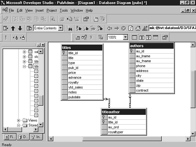
The Titles table has a many-to-many relationship with the Authors table. A title can have multiple authors, and an author can write multiple titles. The junction table for the Titles and Authors tables is the TitleAuthor table. This table primary key contains the primary key from the Titles table as well as the primary key from the Authors table. Figure 10.2 shows a diagram of these three tables.
A many-to-many relationship.
The third type of relationship is one-to-one. In a one-to-one relationship, a row from one table relates to a single row of another table. This relationship really defeats the purpose of the relational model and isn't used very often.
Constraints
You will want to enforce certain rules concerning the columns within your database. Constraints enable you to define the rules for the values of the columns in your tables. Table 10.1 displays the five types of constraints provided by MS SQL Server and their descriptions.
Table 10.1. MS SQL Server constraints.
| Type | Description |
| Check | Enforces valid data values for one or more columns |
| Default | Provides a default value for a column |
| Primary Key | Avoids duplicate or null values |
| Foreign Key | Enforces referential integrity foreign key relationships |
| Unique | Ensures a unique value for a column or set of columns |
Indexes
Indexes provide fast access to rows in your database. A database index is very similar to the index in this book. You use the book index to find the page for a certain topic and then turn to that page number to read about the topic. The database index works in much the same way by storing a pointer to certain data in your database. The index consists of a column or set of columns within the table. You should only establish indexes for data that the user will access frequently. While indexes provide fast access to data, they absorb disk space and slow the speed of inserts, changes, and deletions into the database.
Getting Started with the Database Designer
The Database Designer provides a very flexible and intuitive environment for working with your database objects. Database diagrams provide the main interface for creating and maintaining your database objects. A database diagram visually depicts the columns, tables, and the relationships of the tables within your database. I will talk about diagrams in the next section, "Visualizing Your Database."
I prefer to use Visual InterDev to create a database project for the specific purposes of administering my database. In this way, you can separate the development tasks from the database administration tasks. You can determine what is best for your project based on personal preference.
To create a database project, select New from the File menu. The New tabbed dialog window is then displayed. Choose the Projects tab and select Database Project from the list. Type a name for the new database project and click OK. You will be prompted to add or select a database connection similar to the database connection that you added during Day 8, "Communicating with a Database." For purposes of this example, I selected the Publishers datasource that I established earlier. This data connection creates a live connection to your database that you can then use to manage your database.
NOTE: You can choose to add the database connection after you have created the project by choosing Add Data Connection from the shortcut menu.
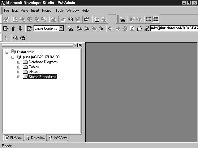
Figure 10.3 shows the database project for the Publishers database.
A sample database project.
Once you have created a database project, you are ready to get started. The next section provides an overview of database diagrams and their relevance to managing your database.
Visualizing Your Database
The Database Designer uses diagrams to graphically depict the objects in your database including tables, columns, constraints, and indexes. The database diagram will also show the relationship between tables in your database. You can make modifications to these objects as well as the table relationships by using the database diagram. Your changes won't affect the database until you save them, enabling you to create what-if scenarios for the database.
When you're finished with your modifications, you can choose to either update the database, save the changes to execute later, or cancel the changes. If you choose to save the changes for later use, the modifications will be saved in a Transact-SQL script. I will provide more detail on the use of these scripts at the end of today's lesson, in the section "Utilizing SQL Scripts."
Exploring a Database Diagram
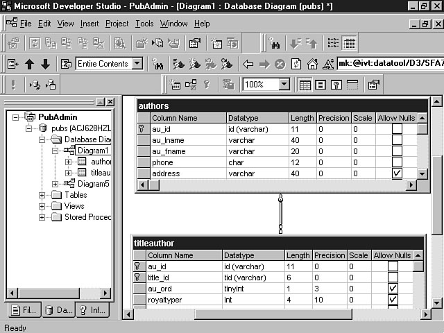
Database diagrams are saved in the Database Diagram folder within your project. You can expand this folder in the Data View to see all of the database diagrams for your database. A database diagram will typically contain one or more tables. Figure 10.4 displays a diagram for the Authors and TitleAuthor tables.
A database diagram.
As you can see from the picture, the Authors table has a one-to-many relationship with the TitleAuthor table. You learned about the relationship symbols during yesterday's lesson. Each table is represented by a grid that contains its columns. A key symbol in the box next to a column designates the keys for each table. In the Authors table, there is a key beside the au_id (Author ID) column. The key for the TitleAuthor table is a combination of the au_id and the title_id columns.
Table 10.2 defines each of the columns within the database diagram grid.
Table 10.2. Database column properties.
| Column Property | Description |
| Column Name | Name of the column |
| Datatype | Type of data to be stored |
| Length | Length of the column (determined by data type) |
| Precision | Maximum number of digits used or maximum length of column for alphanumeric columns |
| Scale | Maximum number of digits to the right of the decimal |
| Allow Nulls | Specifies whether null values can be allowed |
| Default Value | Sets a default value for the column |
| Identity | Column that will contain a system-generated value |
| Identity Seed | Initial value for the system-generated column |
| Identity Increment | Increment for the system-generated value |
NOTE: The length is defined automatically when you assign a data type for a column. You can change the length of some fields, including binary, char, varbinary, and varchar.
Understanding Database Diagram Properties
You can access and change the properties for the tables, indexes, and relationships for your diagrams by using the Properties dialog window. This window is a tabbed display dialog window that contains the properties for each of these objects. The following section explains the property fields for each of these database objects.
Table Properties
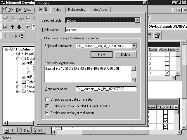
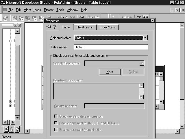
You can access the properties for your tables by selecting the table and clicking the right mouse button to display the shortcut menu. Choose Properties from the list of menu items. Figure 10.5 demonstrates the available properties for a sample table.
Setting the table properties.
This window enables you to view and change the properties for a particular table. The Selected table drop-down listbox enables you to choose another table from the list and view its properties. This listbox only displays tables that are included in the current database diagram that you are working in. The Table name field enables you to view and change the name of the selected table. The bottom half of this window enables you to see the selected check constraints for the table and its columns. The Selected constraint drop-down listbox enables you to choose a column that contains a check constraint. See Table 10.3 for details.
Table 10.3. The Selected constraint drop-down listbox.
| Property | Description |
| New push button | Enables you to create a new check constraint for the table |
| Delete push button | Deletes the currently selected check constraint from the database |
| Constraint expression field | Use it to enter the Transact-SQL syntax for the check constraint |
| Constraint Name | Enables you to view and change the name of the check constraint |
| Check existing data on creation | Applies the constraint to existing data in the database if the checkbox is enabled |
You can check the Enable constraint for INSERT or UPDATE to apply the constraint to all insertions and updates into the database. The Enable constraint for replication enables you to use the constraint for replicating the table to a different database.
Relationship Properties
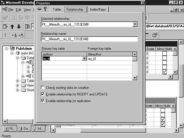
The Relationship Properties dialog window enables you to change the properties of the relationships of the tables contained in your database diagrams. Figure 10.6 shows the fields that are contained on this window.
Setting the relationship properties.
The first field on this page displays the Selected relationship. You can choose another relationship from the drop-down listbox.
The Relationship name field enables you to change the name of the currently selected relationship.
The Primary key table shows the name of the primary key table in the relationship and the columns that make up the primary key.
The Foreign key table displays the name of the foreign key table in the relationship and the columns that make up the foreign key.
The next three checkboxes are similar in meaning to the checkboxes contained on the Table Properties window. These checkboxes apply to the foreign key in the table relationship. If the Check existing data on creation is enabled, the constraint is applied to existing data in the database when the relationship is added to the Foreign key table. You can check the Enable constraint for INSERT or UPDATE to apply the constraint to all insertions and updates into the Foreign key table. Enabling this checkbox also prevents a deletion of a row in the Primary table if a related row in the Foreign key table exists. The Enable constraint for replication enables you to use the constraint for replicating the Foreign key table to a different database.
Index/Keys Properties
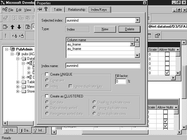
You can use this dialog window to view and change the keys and indexes for the tables within your database diagrams. Figure 10.7 shows the options that are available in this dialog window.
Setting the properties for the indexes and keys.
As you can see from Figure 10.7, the Selected index field displays the indexes and keys for the selected table. The Type display box located below the Selected index field denotes whether you're viewing a primary key, unique key, or index for the selected table. The Column name grid displays the column names that are included in the index or key. You can add, change, or delete columns from the list by using the New and Delete push buttons. The Index name enables you to establish a name for the index.
The Create UNIQUE checkbox enables you to create a unique constraint or index for the table. If you create a unique index, you can choose to ignore duplicate keys. You can use the Fill Factor field to specify how full to make the index page within the database. This field is used by database administrators to fine-tune performance of the database. The Create as CLUSTERED field enables you to create a clustered index. A clustered index provides faster access to data than non-clustered indexes.
New Term: A clustered index is a type of index in which the logical order of the key values of the index is the same as the physical order of the rows containing the keys.
The remaining checkboxes on the Index/Keys dialog window enable you to further specify attributes of the clustered index, and are pretty self-explanatory.
Creating and Editing SQL Server Objects
So far, you have learned about the types of database objects that you can manipulate as well as how database diagrams provide the main method for working with these objects. In this section, you are guided through the process of creating and saving a database diagram. The lesson also teaches you how to create and maintain the database objects within your diagrams.
Creating a Database Diagram
Before you can work with the database objects, you need to create a database diagram. You can create a diagram in one of two ways. First, you can select a table and click the right mouse button to display the shortcut menu. Choose Design from the list of menu items to create a database diagram with the selected table. This diagram will be a single table diagram for the selected table.
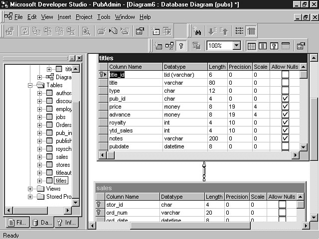
The second method involves selecting the Insert menu and choosing Insert Database Item from the menu items. Select Database Diagram from the list of choices, and a blank database diagram will be created. You can then drag and drop tables from the Data View to add additional tables into the diagram. Once you drop the table into the diagram, the relationship between the tables will be automatically depicted. Figure 10.8 shows a database diagram for the Titles and Sales tables in the Publishers database.
A sample database diagram.
Creating a New Database Table
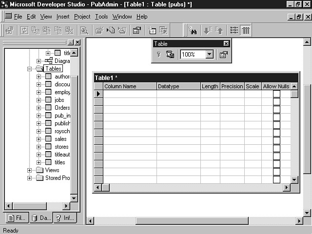
You can click the New Table icon on the Database Diagram toolbar to insert a new table into your database diagram. This icon is the icon furthest to the left on the toolbar. After you click this icon, a blank table is displayed, enabling you to enter the column names and properties into the grid, as displayed in Figure 10.9.
To enter a name for the table, select the table and click the right mouse button to display the shortcut menu. Choose Properties from the list of menu items to display the Properties dialog window. Select the Table tab and enter a new name for the table in the Table name field. When you change the name of the table using this field, the Selected name drop-down list- box changes to reflect the new name of the table that you enter. Figure 10.10 displays the Table Properties window with a newly created table that has been renamed.
TIP: There are several other methods for creating a new database table. First, you can right-click the mouse and choose New Table from the shortcut menu. Another method involves selecting the New Database Item from the Insert menu and choosing Table from the list of database items. You also can right-click the Tables folder in the Data View and choose Insert New Table from the shortcut menu.
Creating a new table.
Renaming the table.
Defining the Column Properties
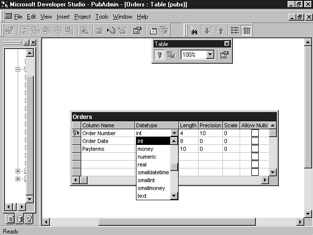
Once you have created the table and given it a meaningful name, you can enter the column names and properties. You can use the Tab and arrow keys to navigate within the fields in the grid. An arrow in the box to the left of the column name denotes the current row that you are inserting within the grid. Once you enter a column name, you can choose a data type from the drop-down listbox in the Datatype field for the column. Figure 10.11 shows an example of some of the available data types using the Database Designer.
Setting the data type.
After you enter the columns for the table, you need to set the key values for the table. Select the row that you want to be the primary key and click the Set Primary Key icon on the Database Diagram toolbar. If the primary key of the table is a combination of columns, you need to select all of the columns that are a part of the key and then click the Set Primary Key icon. To select multiple rows in the grid, click the mouse in the box to the left of the Column name field to highlight the first column row. Then click the Shift+Down Arrow key combination to highlight the next column row. Repeat this step until you have highlighted all of the column rows for the primary key and then click the Set Primary Key icon from the Database Diagram toolbar. A key indicator is displayed next to the columns that you designate as the primary key.
Saving Your Database Changes
The final step to creating your new database table involves saving the changes to the database. You have learned over the last couple of days that the database connection that you establish is a live connection. In other words, the actions that you perform have an immediate effect on the database. The Database Diagram gives you the option of directly updating the database or saving the changes for later. To save a newly created table, you have several available options. First, you can choose Save from the File menu. You will be prompted to enter a name for the diagram you used to create the new tables. Once you enter the name and click OK, the Database Designer inserts the new table or tables into the database.
NOTE: The Save All command from the File menu has the same effect as the Save option. Both of these menu commands will perform immediate updates against the database.
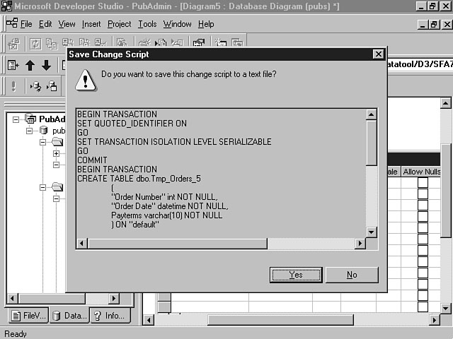
You also can choose Save Change Script from the File menu, which saves the SQL script to a text file that you can execute against the database at a later time.
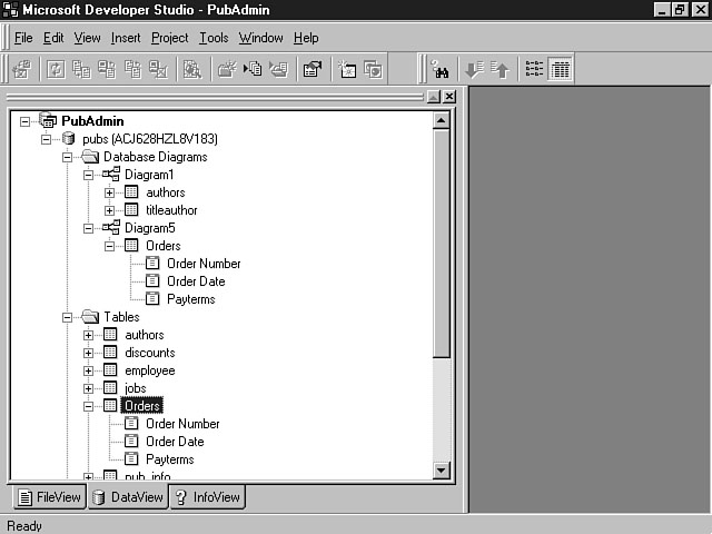
Figure 10.12 shows the results of saving the Orders table against the Publishers database.
Saving the new table.
Working with Diagrams and Tables
You can use the Database Designer to view the relationships of the tables in your database. You also can use the Database Designer to modify existing table relationships and properties. To open an existing database diagram, right-click the mouse on the selected diagram from within the Data View and choose Open from the list of menu items. This action opens the database diagram, enabling you to work with the tables contained in the diagram. You can make changes to the column properties as well as the relationships between the tables. You also can add new tables to the diagram, as explained in the previous section. Once you have made your modifications, you need to save your changes to the database. You can either save these changes immediately to the database or save the changes to a text file for later use.
Utilizing SQL Scripts
In the previous section, you discovered that you can execute immediate updates against the database. You also learned that you can save these changes in a text file to be executed at a later time. These files contain Transact-SQL commands that perform administrative functions against the database.
SQL scripts can be useful, especially if you have to execute the same commands repeatedly against a database. These scripts also can be useful for creating the same databases and tables for separate development, testing, and production database environments. You learned about the benefits and use of these environments on Day 3, "Design and Development Considerations." A good DBA learns the benefit of SQL scripts very quickly in life. It only takes having to delete a table and re-create it manually one time to see the benefit of an automated script that performs this function for you.
Saving the SQL Script
Earlier today, you learned how to create and modify tables. The last step involves saving those changes. The previous example showed you how to immediately update the database with the changes. To save the changes to a SQL script instead, choose Save SQL Script from the File menu. The Save Change Script dialog window displays. Figure 10.13 shows a SQL script for a change to the column data type of an existing table.
The Save Change Script dialog window displays the actual Transact-SQL that will be saved to the text file. Listing 10.1 shows the complete code sample for Figure 10.13.
Examining the SQL Script.
Listing 10.1. Changing the data type of a database column.
BEGIN TRANSACTION
SET QUOTED_IDENTIFIER ON
GO
SET TRANSACTION ISOLATION LEVEL SERIALIZABLE
GO
COMMIT
BEGIN TRANSACTION
CREATE TABLE dbo.Tmp_Orders_4
(
"Order Number" int NOT NULL,
"Order Date" datetime NOT NULL,
Payterms varchar(10) NOT NULL
) ON "default"
GO
IF EXISTS(SELECT * FROM dbo.Orders)
EXEC(`INSERT INTO dbo.Tmp_Orders_4("Order Number", "Order Date", Payterms)
SELECT "Order Number", "Order Date", CONVERT(varchar(10), Payterms)
ÂFROM dbo.Orders TABLOCKX')
GO
DROP TABLE dbo.Orders
GO
EXECUTE sp_rename `dbo.Tmp_Orders_4', `Orders'
GO
ALTER TABLE dbo.Orders ADD CONSTRAINT
PK_Orders PRIMARY KEY NONCLUSTERED
(
"Order Number"
) ON "default"
GO
COMMIT
I'm not going to examine the entire code listing, but I did want to outline a very robust feature of the Database Designer. You can use the Database Designer to change the column data types of tables that contain existing data. This code listing shows the Transact-SQL that creates a temporary table named Tmp_Orders_4. This temporary table is used to insert any data that resides in the Orders table and convert it to the new data type. The original Orders table with the old data type for the Payterms column is then deleted. Finally, the Tmp_Orders_4 table that contains the order information with the new data type is renamed to Orders. The Database Designer creates all this logic for you, which should make DBAs appreciate the robustness of the Database Designer even more.
After you have verified that the SQL syntax is correct, you can click Yes to save the changes for the SQL script. A confirmation message with a default name for the script is then displayed. The name is assigned by the Database Designer and contains the .sql extension. You can edit this file using Visual InterDev as well as any text editor. You also may want to rename the file to conform to any standards that you have established for your project.
Creating and Editing Stored Procedures
The stored procedure editor provides a very intuitive tool for creating and maintaining stored procedures for your applications. Visual InterDev supports the use of the stored procedure editor with MS SQL Server 6.0 and higher and Oracle 7.0 and higher. If you're using MS SQL Server 6.5 or higher, you also can also debug your stored procedures.
Creating a Stored Procedure
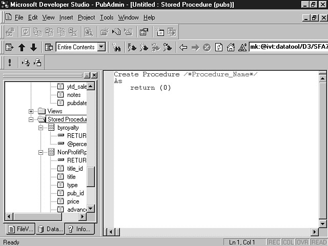
To create a new stored procedure, select the Stored Procedures folder and right-click the mouse to display the shortcut menu. Choose New Stored Procedure from the list of menu items. The stored procedure editor opens and presents a template for creating your new stored procedure. Figure 10.14 displays a sample template for creating a new stored procedure.
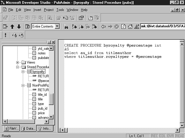
The template includes the Transact-SQL key words CREATE PROCEDURE that signify all stored procedures. Also, the template provides a place for you to enter the name of the new procedure. You can then enter the SQL for your procedure after the AS key word. The stored procedure template also provides a placeholder at the end of the procedure for capturing the return code. After you have developed your stored procedure, you can save it by choosing Save or Save As from the File menu. The Save As option enables you to save the file in a separate text file that is denoted with the .tsq filename extension. Figure 10.15 shows an example of a stored procedure.
Creating a new stored procedure.
A sample stored procedure.
Executing a Stored Procedure
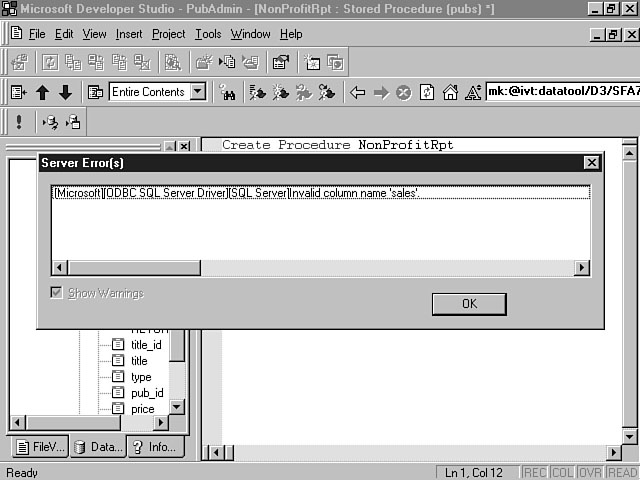
You learned during yesterday's lesson how to execute a stored procedure. Once you have created and saved your stored procedure, you should test the procedure to ensure that it produces the desired results. You can execute the procedure from within the stored procedure editor by right-clicking the mouse anywhere within the stored procedure. Choose Run from the list of menu items. If there is an error in your procedure, the stored procedure debugger displays an error message indicating the mistake, as shown in Figure 10.16.
An erroneous stored procedure.
If no errors are found, the result is displayed in the Output window at the bottom of the Visual InterDev project workspace, as depicted in Figure 10.17.
You still need to make sure that the stored procedure returned the results that you expected. A bug-free procedure does not mean that the stored procedure is accurate. You need to test the procedure to make sure that it meets your application requirements both now and in the future. A stored procedure is usually shared among the developers. Develop these procedures in a manner that can be universally applied across the application. This doesn't mean that you should have one stored procedure that meets everyone's needs. You should, however, create procedures that are targeted to the needs of more than a single developer.
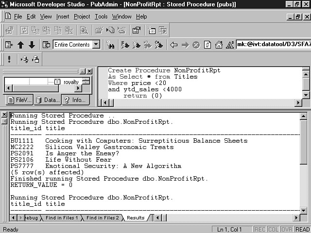
Executing a successful stored procedure.
Summary
Today's lesson concludes the last section focused solely on the database part of your application. You should be able to apply the database principles that you have learned over the last three days toward the other lessons this week and next week. Database administration isn't an exciting pastime, but a good DBA is worth his or her salt. You can use the Database Designer to perform routine database administration and management functions without becoming a full-fledged DBA. The Database Designer provides a visual tool that removes a lot of the mundane chores of managing your database components.
Today's lesson first provided you with an introduction to the Database Designer. You learned about the types of database objects that you can create and manipulate using the Database Designer. Next, you learned how to use database diagrams to create and maintain your database objects. You discovered the usefulness of database diagrams in providing a visual picture of your database as well as a visual tool to manage the database tables and objects.
Toward the end of the day, the lesson focused on the use of SQL scripts. You learned about how the different Save options have an impact on the database and how you can use SQL scripts for database updates in the future. The final lesson for the day taught you to how to create and edit a stored procedure.
Q&A
- Q Does the Database Designer replace my existing database administration tools?
AThe Database Designer is meant to complement your other DBA tools. The Database Designer enables you to administrate and manage database objects once you have created a database. You can use the Database Designer as yet another tool in your DBA toolbox.
What is the difference between an index and a primary key?
AA primary key is used to uniquely define a row in a table. A primary key can consist of a single column or a combination of multiple columns. An index consists of a key value and a pointer to the data contained in the table. An index provides an additional method for accessing data in your tables.
Workshop
Today's workshop focuses on the use of database diagrams. Use the Publishers database included with MS SQL Server to create some database diagrams of your own. Create some new tables to add to the database and practice defining column properties for these tables. Use the examples provided in this lesson as a guide to walk you through these steps.
You also should practice developing a few stored procedures for the Publishers database. This database includes a few examples to get you started.
Quiz
- 1. What is a foreign key?
2. What is the Default Value column property used for?
3. Name three types of column constraints.
Quiz Answers
- 1. A foreign key is a column or set of columns whose value matches the
primary key value of another table.
2. The Default Value property enables you to specify a default value for a column. This property can be used in situations when you want to populate the value of the column if the user doesn't enter a value for the field within the context of your application.
3. Possible answers include- Check
Default
Primary Key
Foreign Key
Unique
- Check
![]()
![]()
![]()
![]()