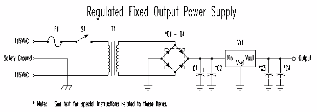


Three terminal regulators
offer many benefits to the electronics hobbist. Low cost, ease of
use, low parts count, and high reliability. Three terminals regulators
have been available for nearly 20 years. They are availiable in a
wide range of voltage, current and performance configurations. Output
voltage configurations range from as little as 1.25 volts to as high as
24 volts. Current output ranges from as little as 100 mA to more
than 3 Amperes. Fixed output regulators provide a very low parts
count solution for a variety of power supply requirements. In recent
years three terminal regulators have been extended in both output voltage,
current, and programability. This white paper will use a standard
fixed output variety which is suitable for nearly all power supply projects.
Most three terminal regulators have internal current and over temperature
sensing. These features when combined with ease of use make power
supply construction easy, effective and reliable.


Transformer Notes:
When selecting a transformer some substitutions may be necessary. Center Tapped transformers may be used if rated as 12.6 VCT or 15 VCT. In the case of center tapped transformer simply use the outer two leads and insulate the center tapped lead. Connect the outer two leads to the diode bridge.
Diode Notes:
Substitutions on diodes are allowed as long as the PIV (or PRV) rating is equal to or greater than listed. This is true of the current rating as well. 1 amp diodes may fail under extended use or transient conditions. Diodes with a rating of 50 PIV may fail under transient conditions and should be avoided. When installing diodes avoid excessive heat during soldering, also leave at least 0.5" of lead length from body to attachment point. Diode bridge assemblies may be used as a substitute, above ratings should apply. It is recommended that the diode bridge be lightly heat sinked for maximum protection against thermal overload.
Capacitor Notes:
Capacitors C2, C3, C4 recommended for increased transient response. C3 is strongly recommended to prevent output oscillations in cases where long lead length exist. Avoid using output capacitor values of greater than 10 uF for C4. Large capacitor values could lead to reverse bias failure of the three terminal regulator during turn-off. Some manufacturers recommend that you place the a reverse bias diode across the Vin and Vout terminals of the regulator to prevent this type of failure when using highly capacitive loads. C1 may be increased, however this will increase diode and regulator heat dissipation. You may substitute a combination of 2 - 1000 uF capacitors or 4 - 470 uF capacitors for C1 if the 2200 uF is not available. The capacitors must be placed in parallel with each other. That is to say that the positive leads of the capacitors must be tied together and likewise the negative leads must all be tied together.
Fuse Notes:
Fuse selection is
based on a conservative 400% overload. Use of a larger fuse may result
in component failure. The use of circuit breakers is not recommended.

The power supply should
be assembled with a three prong cord for maximum safety. Ground prong
should be attached to either transformer or project box (if metal).
Length of ground wire should be at least 1" longer than wires going to
switch and transformer. Three terminal regulator should be heat sinked
to back of case (if metal) or attached to metal heat sink. A heat
sink of approximately 5" x 3" high with at least 1" fin depth is recommended.
Insulate three terminal regulator from metal case or heat sink with thermal
insulators. The use of a light film of thermal compound between the
heat sink and the three terminal regulator is strongly recommended.
Be sure to use either a nylon attachment screw or plastic shoulder washer
to completely insulate regulator from case or heat sink.

It is recommended that the project is tested in stages during assembly. Adult supervision is strongly advised. Follow established safety practices and ensure that during repair that the power supply cord is removed from the electrical outlet before proceeding. Words of Wisdom :

Avoid testing the primary
side of the circuit unless absolutely necessary. With a transformer
rated at 12.6 VAC you should measure about 12.6 VAC or more with no load.
After the diodes you should measure about 17 VDC with no load and about
15 VDC under full load conditions. The ripple voltage under full
load should be about 4-5 volts peak to peak. The output voltage of
the regulator should be 5 volts +- 0.1 volts (2%). Between no load
and full load the output voltage should not vary more than about 0.2 volt.
If you fine that it does make sure that the reference pin of the regulator
is wired as close as possible to the ground output terminal of the power
supply. Use at least 18 gage wire for the output and ground connections.
Keep all connections short and direct to avoid ground loops and excessive
voltage drops. Under full load conditions the regulator may be quite
warm, if you can measure it, be sure that it operates at temperature of
less 180 degrees Fahrenheit. This translates into about 80 degree
Celsius which should provide a reasonable margin of safety. If your
regulator runs hotter than this you will need to provide extra heat sinking.
Either increase the metal radiating surface (increase the size of mounting
surface) or use a larger heatsink.
 |
|
| Harris Semiconductor Product Data Sheets |
|
| Motorola Semiconductor Product Data Sheets |
|
| National Semiconductor Product Data Sheets |
|
|
|
|
 |
|
| DigiKey Corporation |
|
|
|
|
|
|
|
|
|
|
|
|
|
|
|
|
| Disclaimer: |
|