This is an old revision of the document!
Table of Contents
Raspberry Pi Explorer Kit
In this page I will tell you about some experiments that I made with the Aerocene Explorarion Tools. I got an exploration kit consisting of the following parts:
- The Raspberry Pi 2 Model B
- One solar panel with litium-ion polymer battery (5000 mAh)
- One Adafruit Ultimate GPS HAT for the Raspberry Pi
- One Miuzei Raspberry Pi camera module (OV5647 sensor, 2592×1944 = 5 Mpixels)
- One LogiLink USB WiFi dongle
- Two BME280 pressure/temperature/humidity sensor
- One Plantower PMS5003 particulate matter sensor
- One USB-to-serial adapter
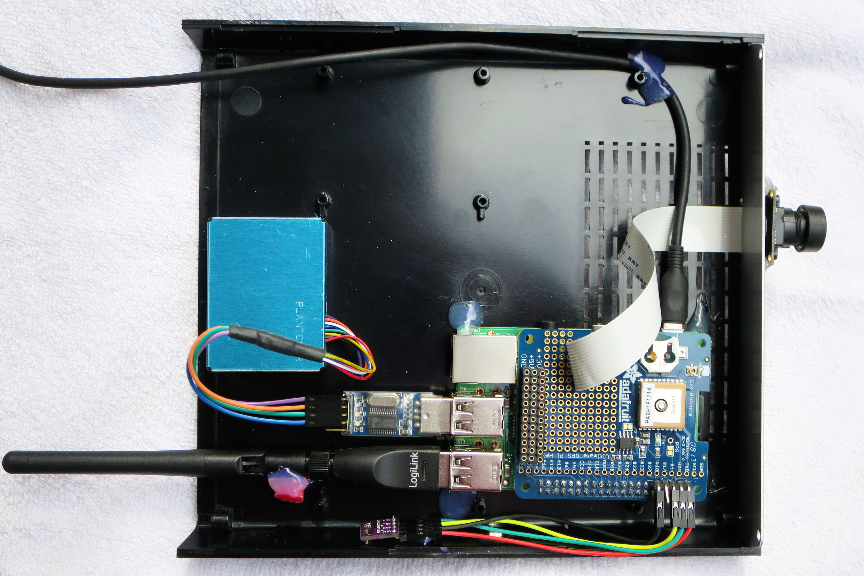
Here it is a photo of the prototype assembled into a plastic case:
Connecting the Hardware
Adafruit GPS unit
The Adafruit GPS unit communicates with the Raspberry Pi using the serial interface which is available on PIN 8 and PIN 10 of the Raspberry Pi, marked as GPIO14/UART0_TXD and GPIO15/UART0_RXD on many pinout schemes. The standrad Raspbian configuration allocate the serial line for a console (boot messages and login prompt), so a special configuration is required to free the serial line. The raspi-config tool will be used for this.
BME280 sensors
The BME280 sensors are mounted on small breakout modules, which provide the I2C and the power interface. The I2C bus is available on the Raspberry Pi at PIN 3 and PIN 5 marked as GPIO2/SDA1 and GPIO3/SCL1. We have to connect also a ground PIN and a power PIN. The breakouts we used are capable to use both 3.3 or 5.0 volt power available from the Raspberry Pi connector. To connect two sensors at the same time, they must use different I2C addresses, to change the default address 0x76 to the alternative 0x77 it is required to cut and solder a track on the breakouts circuit itself.
PMS5003 sensors
The Plantower PMS5003 particulate matter sensor has a serial interface and requires a 5 volt power. If the serial port of the Raspberry Pi is already taken by the GPS module, we have to provide anoter serial interface via an USB adapter. There are several cheap USB to serial adapter, which also provide a pin for the 5 volt power.
USB to serial adapter
As said above, we required this adapter to connect the PMS5003 sensor. The one we used is based on a Prolific Technology PL2303 chip (USB id 067b:2303), which is automatically detected by the Linux kernel and exposed as the /dev/ttyUSB0 serial device.
WiFi dongle
The WiFi connection is provided by a simple adapter based on the Ralink RT5370 chip (USB id 148f:5370). To operate the adapter we need the rt2870.bin firmware (non-free), which is shipped into the firmware-misc-nonfree package. The package is already installed into the default Raspbian Stretch Lite distribution.
Raspberry Pi Camera Module
 The camera mounted in our kit is based on the OV5647 sensor, capable of 2592×1944 pixels (5 Mpixels). The camera has a wide viewing angle of 175°. The camera requires a manual focus adjust, turning the lens mount clockwise or counerclockwise. The focus resulted a bit critical: trying to focus to infinity it resulted that the mere rotation of 1/16 of a turn, can mess-out the focus very badly. Also the quality of the pictures is not exceptional, they miss the crisp level that we would expect from a 5 Mpixels sensor.
Software Setup
We used a GNU/Linux box to download the software and to prepare the micro SD for the Raspberry Pi.
Installing the Raspbian Distribution
Download the Raspbian Stretch Lite 2018-06-27 distribution from https://www.raspberrypi.org/downloads/raspbian/. Unzip and copy the file to the micro SD:
dd bs=4M if=2018-06-27-raspbian-stretch-lite.img of=/dev/sdc conv=fsync
To enable ssh and WiFi at the first Raspberry Pi bootstrap, we created two files into the first FAT partition of the micro SD. The first file must be named ssh and can be empty, the second file must be named wpa_supplicant.conf and should contain the credential to access your WiFi network:
ctrl_interface=DIR=/var/run/wpa_supplicant GROUP=netdev
update_config=1
country=IT
network={
   ssid="MyESSID"
   psk="SuperSecret"
   key_mgmt=WPA-PSK
}
Those files will be seend by the bootstrap procedure and will configure the ssh and WiFi services.
raspi-config
We used the raspi-config tool, which customizes several system configuration files and re-configure some installed packages. Once logged into the Raspberry via ssh, we gained root privileges with sudo su - and launched raspi-config, then we configured the following options:
- Localisation Options
- Change Locale
- en_US.UTF-8
- it_IT.UTF-8
- Change Timezone
- Europe/Rome
- Interfacing Options
- Camera (Yes)
- I2C (Yes)
- Serial
- Login shell over serial (No)
- Serial port hardware enabled (Yes)
The files changed by that configuration are (among others):
- /boot/config.txt
- /boot/cmdline.txt
- /etc/timezone
Adding Extra Packages
To operate the hardware devices and to run our software, we need some extra packages, available from the Raspbian distribution. From the command line, using the root privileges, run:
apt-get update
apt-get upgrade
apt-get install git i2c-tools python-dev python-setuptools python-spidev
apt-get install gpsd gpsd-clients python-gps
Other required software is not included into the official Raspbian distribution, so we will download (and install) from a GitHub respository:
cd /usr/local/src/
git clone https://github.com/adafruit/Adafruit_Python_GPIO.git
cd Adafruit_Python_GPIO
python setup.py install
This procedure will download and install the Adafruit_Python_GPIO library and the pre-required Adafruit_PureIO library. The destination directory of the installation is /usr/local/lib/python2.7/dist-packages/.
Beware to install setuptools and spidev from the official Raspbian packages before this setup procedure, otherwise the procedure will try to download and install those libraries from extra respositories, possibly messing the things a bit.
Hardware Setup and Test
Adafruit GPS
Run the dmesg command and verify that the kernel detected the serial device /dev/ttyAMA0 (this is for the Raspberry Pi 2 models). Edit the /etc/default/gpsd file and set:
START_DAEMON="true"
USBAUTO="false"
DEVICES="/dev/ttyAMA0"
GPSD_OPTIONS="-n"
restart the gpsd service:
systemctl restart gpsd.service
Notice that recent implementations of gpsd (as the one provided by the Raspbian Stretch distro) do not start the gpsd daemon automatically at bootstrap. Instead they start an Unix socket (/var/run/gpsd.sock) and listen there for incoming client connections. Beside that, they terminate the gpsd instance if no clients are connected for some time.
We need instead an ever-running gpsd, because it will provide precise clock information via shared memory to the ntpd daemon. For this purpose the -n option will prevent gpsd to terminate if no clients are connected. We need also to launch a client at least for a short time to fire-up the gpsd instance, e.g. adding this single line in /etc/rc.local:
# Start a gpsd client for a short time, so that gpsd will be started.
gpspipe -r -n 5 > /dev/null 2>&1 &
Now you can verify that the GPS is running and providing position data (place the device in open sky view, it does not work in a closed room!):
gpspipe -r -n 10
{"class":"VERSION","release":"3.16","rev":"3.16-4","proto_major":3,"proto_minor":11}
{"class":"DEVICES","devices":[{"class":"DEVICE","path":"/dev/ttyAMA0","driver":"MTK-3301",
  "subtype":"AXN_2.31_3339_13101700-5632","activated":"2018-09-06T10:17:33.154Z",
  "flags":1,"native":0,"bps":9600,"parity":"N","stopbits":1,"cycle":1.00,"mincycle":0.20}]}
{"class":"WATCH","enable":true,"json":false,"nmea":true,"raw":0,"scaled":false,
  "timing":false,"split24":false,"pps":false}
$GPGGA,101734.000,4351.5026,N,01105.8562,E,2,11,0.84,35.1,M,47.6,M,0000,0000*5F
$GPGSA,A,3,20,26,32,27,18,21,08,16,10,07,11,,1.34,0.84,1.04*0C
$GPRMC,101734.000,A,4351.5026,N,01105.8562,E,0.27,348.07,060918,,,D*6E
$GPZDA,101734.000,06,09,2018,,*52
$GPGGA,101735.000,4351.5025,N,01105.8562,E,2,11,0.84,35.1,M,47.6,M,0000,0000*5D
$GPGSA,A,3,20,26,32,27,18,21,08,16,10,07,11,,1.34,0.84,1.04*0C
$GPGSV,4,1,14,27,78,333,13,10,66,118,26,20,51,065,20,16,45,197,17*77